![]()
![]()
![]()
![]()
![]()
![]()
The PNG Short Passenger Car Kit
Update 3-15-2018
My trip to California is complete. Got the taxes done, played with the kids and grandkids and visited old friends. As all of you that have built a PNG kit know, a complete frame is included with all kits. It's far easier for me to create a perfectly square frame in my shop than to provide the customer with lumber and a jig and hope for the best.
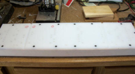
So, for the short passenger cars, I start with a a 6" wide by 24" long sheet of 1/2" thick UHMW. This is the material most often used as a cutting board.
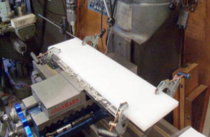

A sheet of UHMW in the vise and getting drilled with a precision .250" drill. I only wish I had room in my shop for this big guy!! The 3 red circled holes are goofs. I read the wrong X & Y coordinates. I guess I'm human!!
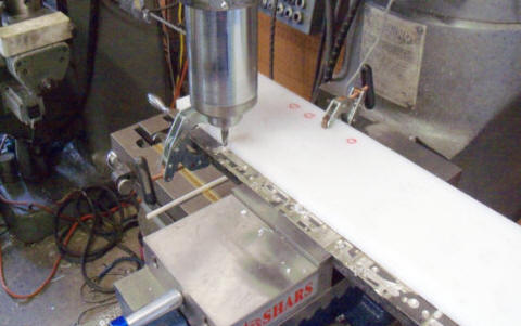
All the holes drilled. In the left picture and a ball end mill is run across the width. This provides a slot for a screw driver to slide in under the frame and pop it off the jig easier. A few of the 1/4" Delrin pins needed knurling so I can pull them out easily.
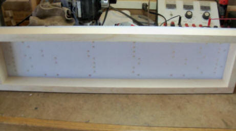
I mount the UHMW on "white wood" 1" X 2" board. Not really sure what white wood is, some kind of southern pine I think, sold at Home Depot here in Colorado.
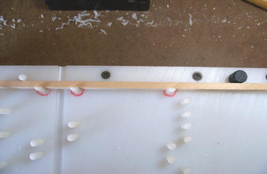
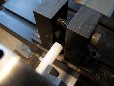
Here's my goof's. The 3 holes with red circles are .110" to close so I milled off .110" from one side of the 1/4" Delrin rod. The green peg on the top right is to correct a hole that was 1/8" to far away. So it's a 1/2" rod with one end turned on the lathe to 1/4". I have a dozen frame jigs for the various kits I've produced over the years. I might have 2-3 without "fixes". Hence, when producing a new kit, I call them the first cut, second cut and so on until I have it right. The other black circles are the tops of sheet rock screws that fasten the UHMW to the wood 1" X 2".
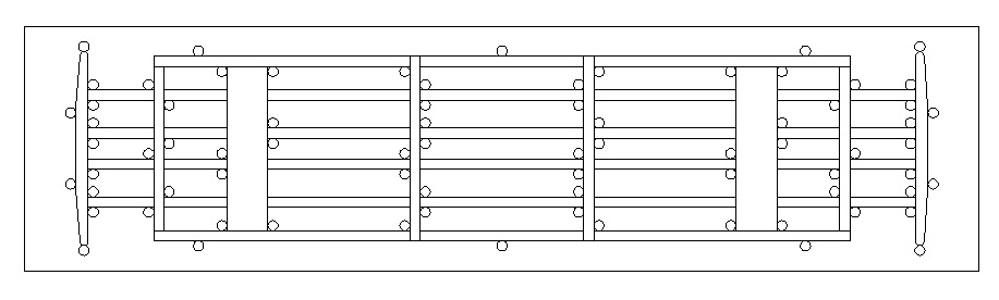
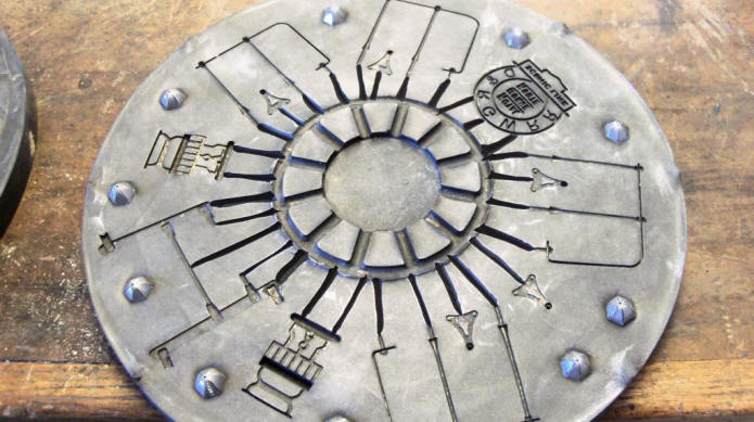
This is the CAD drawing with holes for the Delrin pegs.
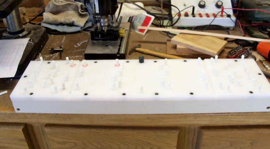
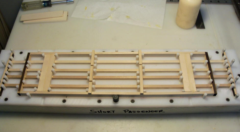
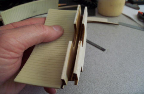
Finished jig with pins inserted. The long groves about 1/4 of the way in on both sides are for a screwdriver to slide in under the glued and nailed frame to pop it off the pins and free of the jig.
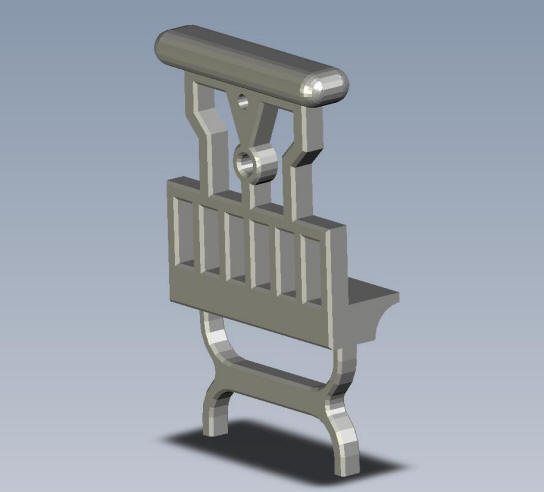
I've also been drawing up the CAD for the coach. This is the master CAD that other pieces will be derived from.
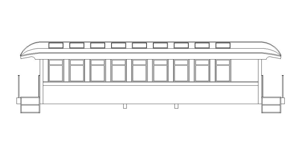
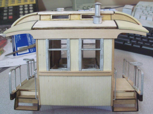
To be perfectly clear about this kit, no narrow gauge railroad had short passenger equipment. This will be a freelance kit. The Sierra Railroad in California has a short coach and combine in standard gauge. They had them made for one of their branch lines that had exceptionally tight radius curves. Pictures of those 2 cars are on the previous page. As drawn, this kit will be 20" long from platform end beam to platform end beam. The real coach had 9 windows so I've done my best to represent that in this kit. I've also made the height and width the same as Accucraft's J&S coach so if they were run with the Accu cars, they would look the same only shorter.
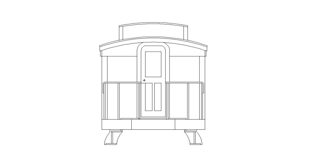
Here's the end drawing of the coach.
I engineered the cars to use Kadee "E" type of couplers because they are the only coupler out there with enough swing to work with the cars on medium curves. The couplers are the number 906. I will order them from Kadee in the rust color to save us from having to paint them and possibly foul up any moving parts.
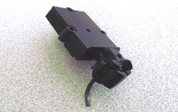
The cars are also engineered for the Aristocraft short passenger trucks. I have several cases of these trucks on hand and they were always planned to be incorporated in these cars.
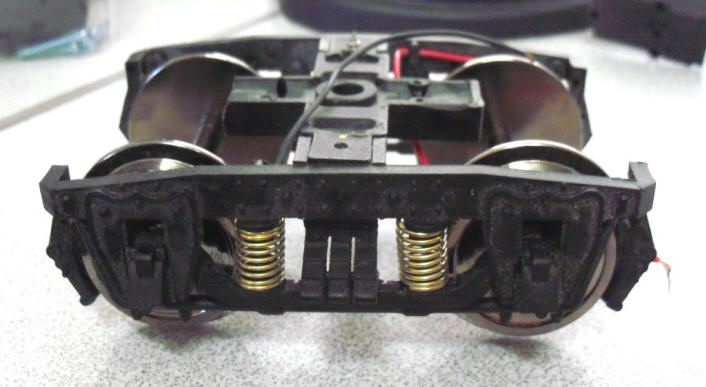
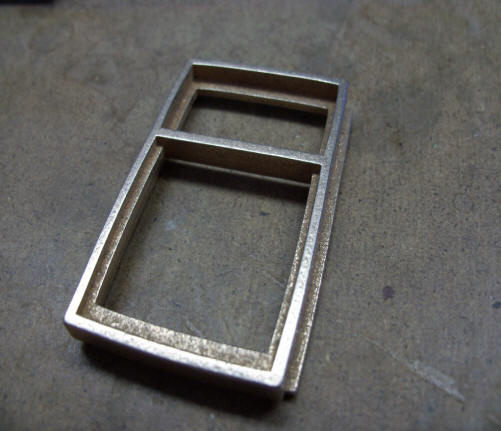
Aristocraft Short Passenger Trucks
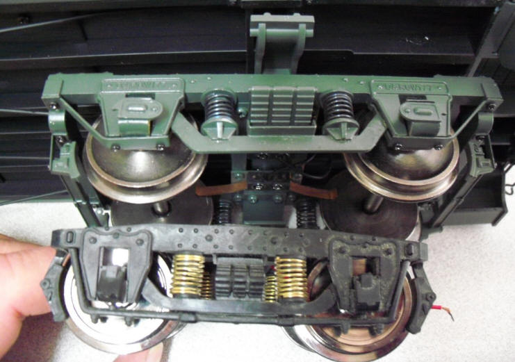
As compared to Accucraft J&S trucks.
I expect to have the frame jig completed in the next 30 days and will work on the CAD drawings that will drive the laser so we can get a look at how this will come together. I'm working with Bob Hartford for some 3D parts to use as masters for the roof ends and other white metal parts I don't currently manufacturer. In return for Bob's help, I'm supplying him with some of my PNG parts that he needs. Bob was here in late August and I walked him through my methodology in kit manufacturing and we compared ideas on several items. Always a good thing when we can work together!!
I did have one suggestion from a follower that thought maybe using Trackside Detail brass end handrails would be good. This will be a set of 4 cars. 2 coach, 1 combine and 1 baggage. Using TD's brass rails will add almost $100 to the cost of the 4 kits. What I think I may do is match the post holes in the end beam for the end rails with the same dimensions of the TD holes but supply white metal rails in the kits. If you decide to upgrade to brass, you may do so at your expense. I'm still chewing on seats. But I'm also trying hard to keep the cost in the $650-$700 range for the four kits. Everything I need, trucks, couplers, resin, wood, brass and white metal alloy keep getting more and more expensive.
More to follow .............. soon I hope. If you have any ideas or comments, feel free to shoot me an email. I am getting a little feedback and or questions. First of all, the Aristocraft trucks are not ball bearing and the way they are designed, there is no way to bearing them. But, they seem to roll fairly well. I don't think an electric or live steam engine will have any problem pulling 4 cars. Still chewing on any sort of interior. Phil 3-15-18
March 21, 2018
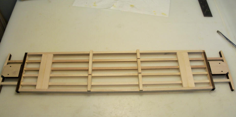
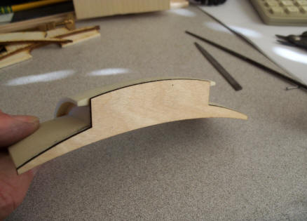
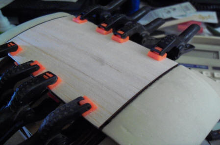
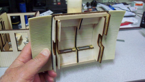
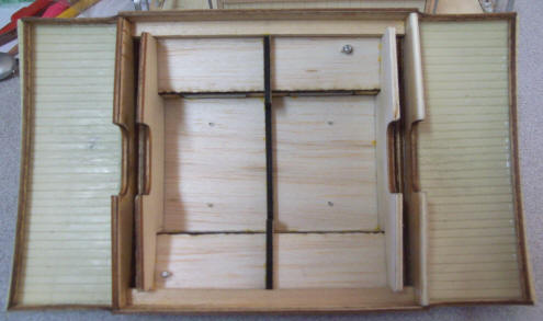
With the frame jig finished it's time to cut some wood and test it out.
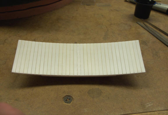
A bunch of basswood sticks cut to length and laid into the jig. The platform end beam and the car body end beam had to be laser cut.
Doing this takes more time but is far stronger than if I cut short little blocks to fit between the 4 center sills.
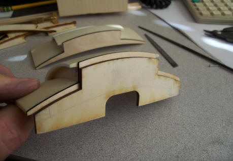
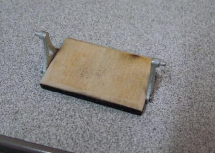
Out of the jig with all nailing finished. Coupler blocks glued to the bottoms of the end platform sills.
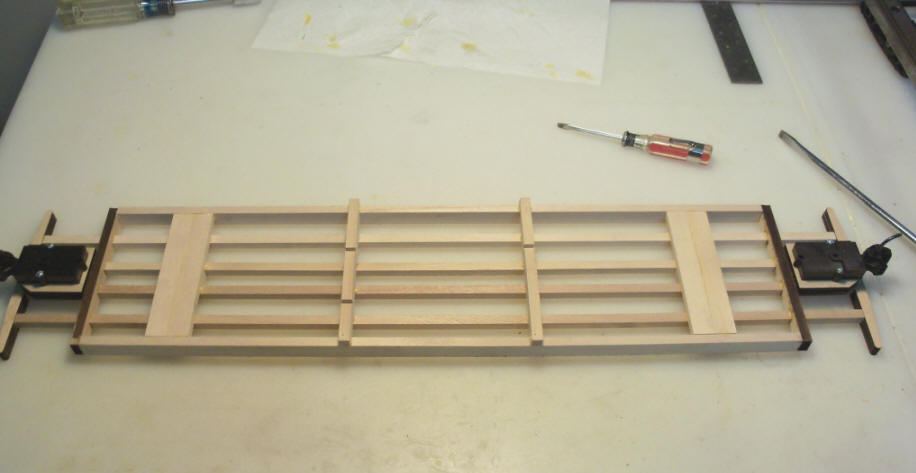
Couplers attached. These are the "E" series 609 couplers from Kadee
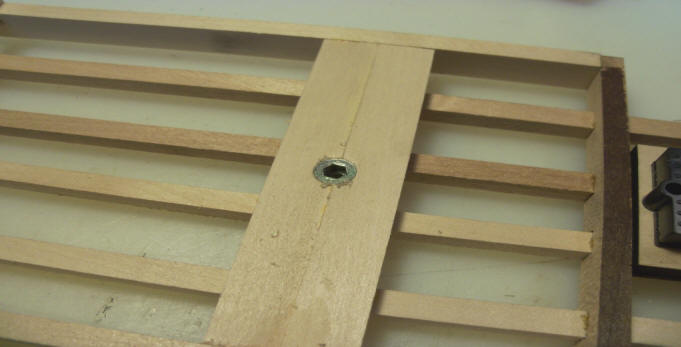
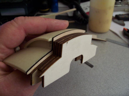
The body bolster drilled and the 8-32 threaded inserts screwed in.
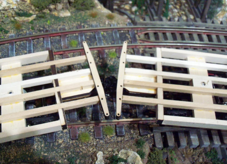
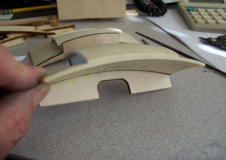
This picture was taken on the tightest curve on my layout. It's approximately 9-1/2 foot in diameter. I mounted the couplers back about 1/4" hoping for a closer coupling of the cars. The 609 coupler shank and knuckle extend approximately 1/4" out from the gear box when pulled. At rest, the shank and knuckle pull back in. This picture is of two frames just sitting on the curve. About 1/2" between the closest points of the end beams.
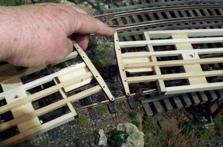
Pushing the cars apart with my fingers to get the maximum extension is approximately 1". Best guess on this test, the car might take a curve of 8' diameter but I don't have any curved track that tight to test them on.
Next up for me is to work on the CAD drawings for the sides and ends. For those of you that purchased the MOW caboose, you know I designed that car with double thickness sides and ends. The inner walls had interlocking tabs at the ends for strength. I plan on using the same methodology for these cars. More next time. Phil
5-10-2018
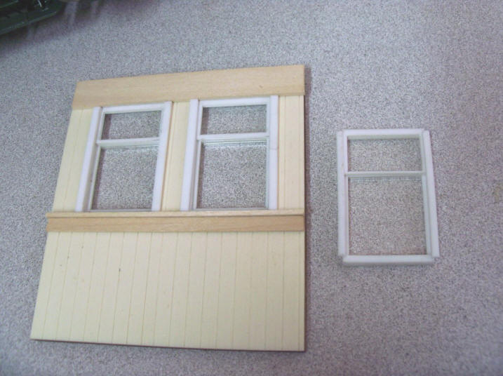
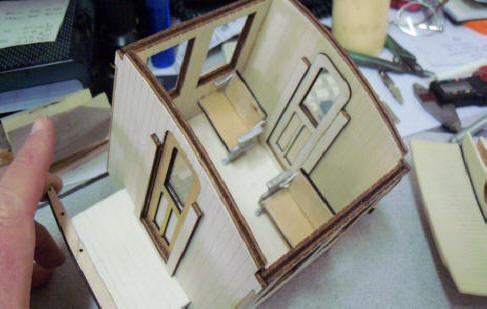
Been typically busy with other projects. But I have had time to work on the CAD for the car sides. Before I can finalize the sides, I have to know the size and placement of the windows. I don't have any windows in my inventory to use on this project so having to re-invent the wheel. I drew up the dimensions of what I wanted and then made 4 separate layers to represent the window. I then lasered each layer from 1/16" white acrylic sheet. Windows from 1/16" clear Lexon sheet. I glued each layer on top of the previous and made a mockup of a partial car side. Here's how it turned out.
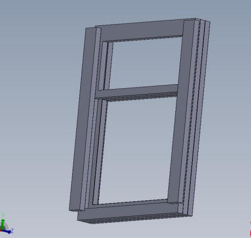
I'm satisfied with how they came out so the next step is to get my 2D drawings converted into a single 3D drawing and get it printed in a resin that will withstand the vulcanizing process so that I can cast these in white metal. I don't really have a feeling for how long this will take so stay tuned!! Phil
5-17-2018 I got the 3D drawing back and approved it. Now it's off to the printer. I needed to order 9" rubber disc for vulcanizing. Producing a kit is complex!! Phil
6-7-18 UPDATE
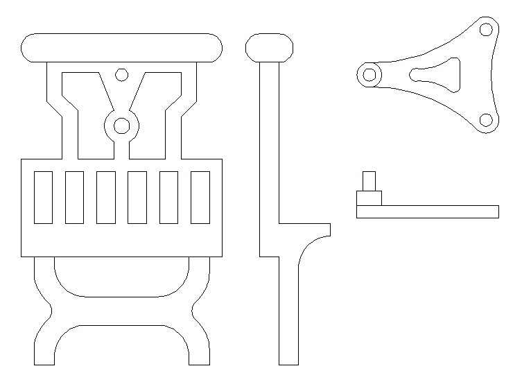
After some careful thought, I'm going to give adding internal seats to the coach and combine cars. To that end, I drew up a composite (in my mind) of pictures I've taken over the years of various passenger car seats plus those made by other modelers. Here's a 2D drawing I made.
Then I downloaded a 3D CAD program called Design Spark Mechanical and beat my head against the wall for a few hours but was able to get the 2 parts 3D'd. There's the seat end and the backrest bracket that will allow the backrest to flip back and forth. So here are the two 3D drawings I put together.
The bracket pin fits into the hole just below the arm rest and the 2 holes in the other end of the bracket are for escutcheon pins to secure the backrest, at least that's the plan. I'm hearing that the parts have been 3D printed and the first mold is being made. First test casting will be approved before a production mold is made. I intend to make these parts in white metal. Fingers crossed this works out. Phil
UPDATE 9-24-2018
I now have white metal castings of the seat components and the windows. I know some manufactures are shifting from machining brass for the white metal spin casting to 3D drawing of the parts. Probably the biggest hurdle is printing the part in a material that will withstand the vulcanizing process. If you're unfamiliar with it, I have a basic set of pictures in my rolling stock pages. Go to the Drop Bottom page and then the development page. While the page covers a lot of part making and building up the prototype, there is a good run of pictures of vulcanizing a set of 9" molds for the white metal spin casting.
Most 3D printed resins will only withstand 175 to 200 degrees F before melting or otherwise self destructing. There have been developments in the rubbers with some silicon based vulcanizing down to 225 degrees F. While Shapeways is an excellent place for the hobbyist to get something printed reasonably, I've not given them much thought until now. The 3 parts I had printed through a friend, cost me dearly and those parts became sacrificial during vulcanizing. They leave behind good cavities so not all was lost. White metal was cast into those cavities and used in a secondary production mold which I now have. But ...... I'm old school and really feel secure when I have all those masters that can be used over and over as all my brass masters I've made over the years. I spent an evening on the Shapeways website reading about all the materials they can print your project in. Like ...... steel !!! or they can print your part in wax and make a lost wax casting in either brass or bronze. Both the steel and brass / bronze parts can withstand over 1,500 degrees F. Not really cheap like the frosted detail plastic parts I purchased for the destroyer I built (Phil's Desk button), but, compared to heavy duty resin (for vulcanizing) and the special low temp casting rubbers or spending days or weeks machining brass, very affordable. So, on with the show.
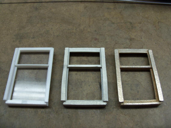
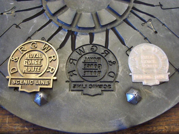
This is the progression of the windows. On the left is 4 layers of acrylic I lasered out and glued together to get a "feel" for how the windows would look. In the middle is the white metal casting of the 3D model I made and sent out for the production mold. A little dis-shaped but a very smooth finish. The right windows is the steel Shapeways printed window. They're made by starting with a thing layer of stainless steel dust that the print head deposits tiny drops of glue. The piece is built up layer after layer until complete. The part which is now very fragile, Shapeways says like wet sand, is carefully removed and fired in an oven and infused with bronze. I'd sure love to get a tour of the Shapeways facility!! Anyway, the finish is a little rougher than the fine white metal casting. I'm leaning towards cleaning up and straightening the white metal castings and making a another production mold using them as the masters. White metal will melt at 450 to 600 degrees F and vulcanizing is 275 to 300 degrees F.
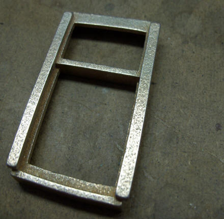
Front and back of the Shapeway steel print. You can see that they are not perfectly square. I may see if I can true this up. I have no idea if it will bend or if it will break when I try. In a way, I kind of like the rough surface. Especially for cast iron but not so much for wood detail.
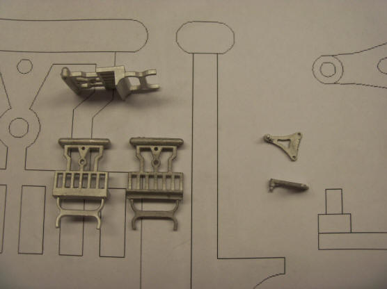
Here are the white metal castings from the production mold.
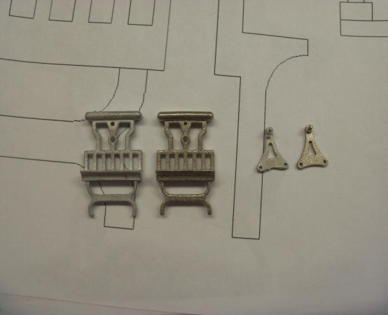
Here's a comparison of the white metal on the left and the Shapeways steel print on the right of both parts.
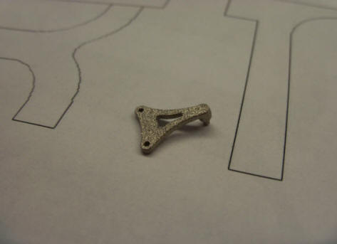
Inside and outside of the 3D printed steel chair end. These were cast iron in the 1:1 prototype and I really like the roughness these have. When I had them printed, I had a choice of finish. I chose the nickel polished finish as it was no extra costs.
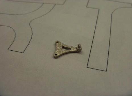
This is the backrest rocker arm. Not as fine detailed as the prototype but I don't like fragile parts and the feedback I get from customers, they don't like them either. Again, I sure like the rough finish. I have vulcanizing rubber on order and look forward to using these parts as masters to see how the white metal will cast.
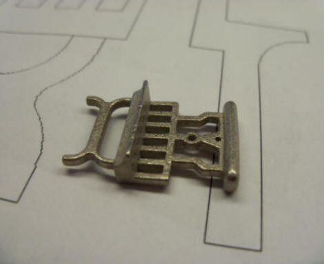
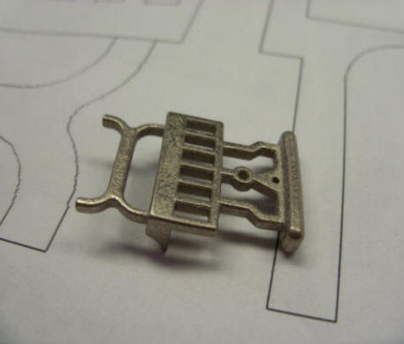
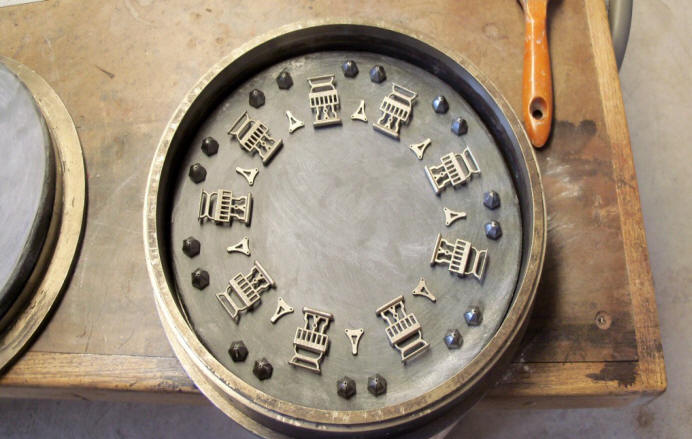
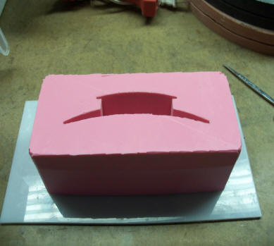
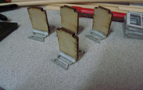
And, the purpose of all this is to make this.
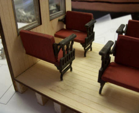
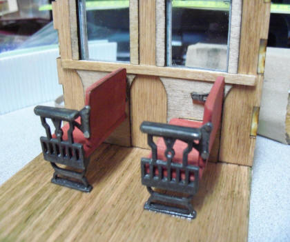
The seat bottom and back are lasered wood, painted with a brick red acrylic paint. The seat backs swivel to the position you want.
Here's a YouTube video of them being rocked back and forth.
Oct 14, 2018
First up, I moved the parts for the water tank project from here over to "Phil's Desk". All tank and just plain old 3D projects will be there in the future.
Several have emailed me about the platform handrails. Trackside Details makes a set of 4 brass South Pacific Coast handrails for $22 + S&H. Part number is TD-253. I bought a set so that I could match the drill pattern for the post into the end beam. Several had thought adding the TD parts would be better, i.e. brass is stronger than white metal. Very true but supplying 4 sets would add $100 to the cost of the 4 car set. So, I will supply white metal handrails and the modeler can upgrade or not to the brass. Hole patterns will match.
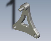
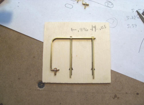
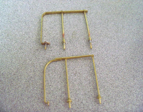
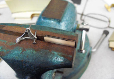
First thing I did was draw up a handrail with the same footprint and laser it out.
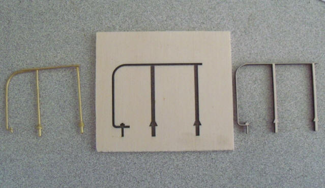
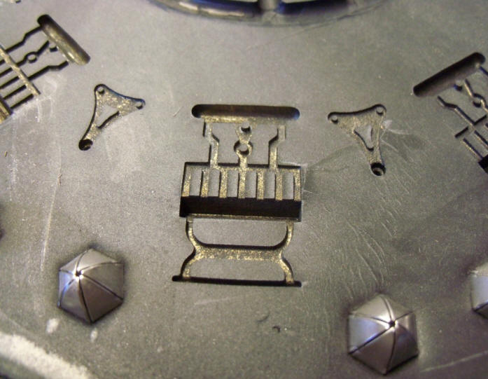
Left is the TD-253. Center is my jig / template. Right is what I lasered out of the jig. The details lasers can do is pretty cool!!!
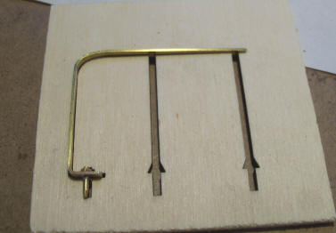
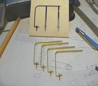
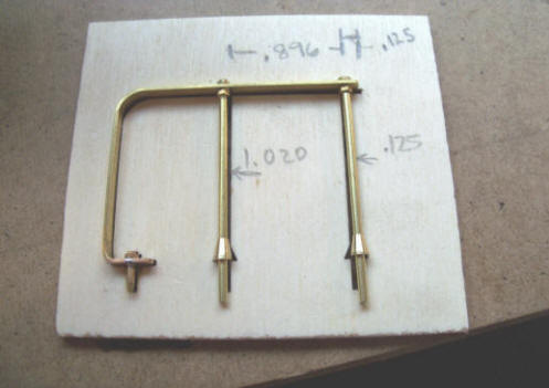
Using the jig, I bend up 4 brass bars and drilled and soldered in 4 PNG NB's
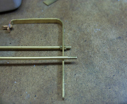
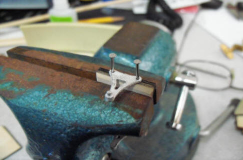
Then I ran 8 pieces of 1/16" brass rod through my 0-80 die, drilled holes for the rod in the rail and screwed them on with 0-80 nuts.
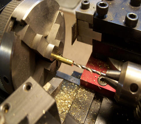
With the 8 handrail post screwed onto the rails I centered drilled 1/8" brass rod for the tapered feet for the post.
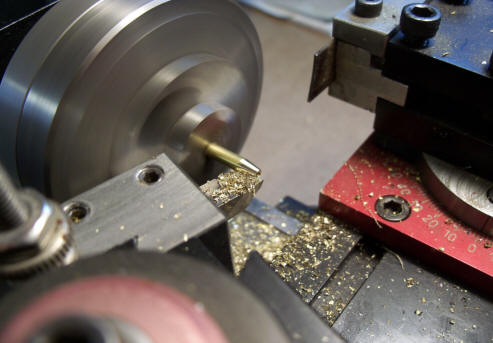
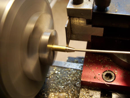
The end of the 1/8" rod is tapered and then "parted" off. I stuck a wire in the end so when it separated from the rod it won't go flying off to the hinterlands.
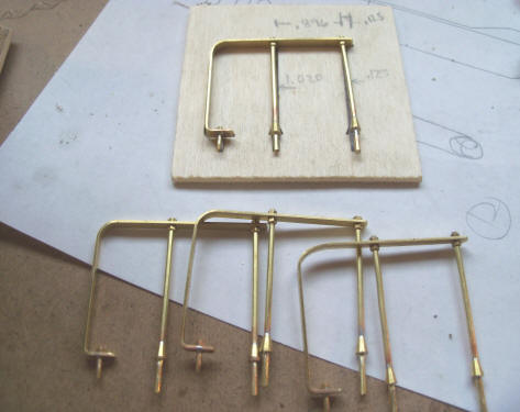
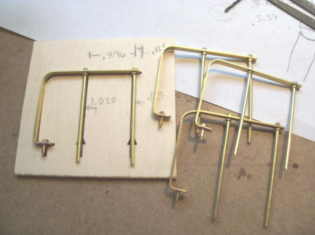
Test fit and final soldering. Ready to have a mold vulcanized of them.
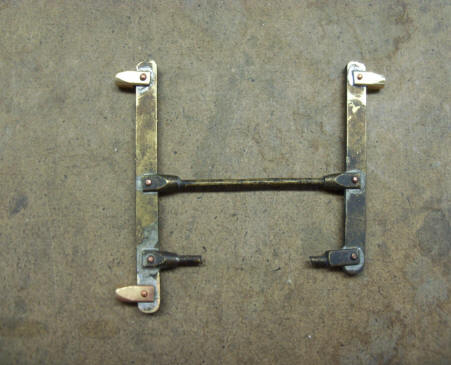
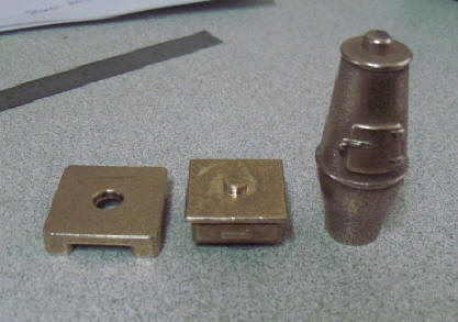
Left photo top is one of my "masters" for the handrail and below is the TD-253. Right photo might look a little familiar to those of you that have built any of my MOW kits. This is the brake lever that fits over the cylinder. The 3 clevis that I drill for 1/16" brake rods were too small and gave me fits drilling them. Drill would brake out and the part ruined and tossed back into the melting pot. You'd think I'd of fixed it to make life easier. Well, now I have!
I still have more of the chair parts being printed at Shapways before I make molds for them. More next update. Phil
Oct 21, 2018
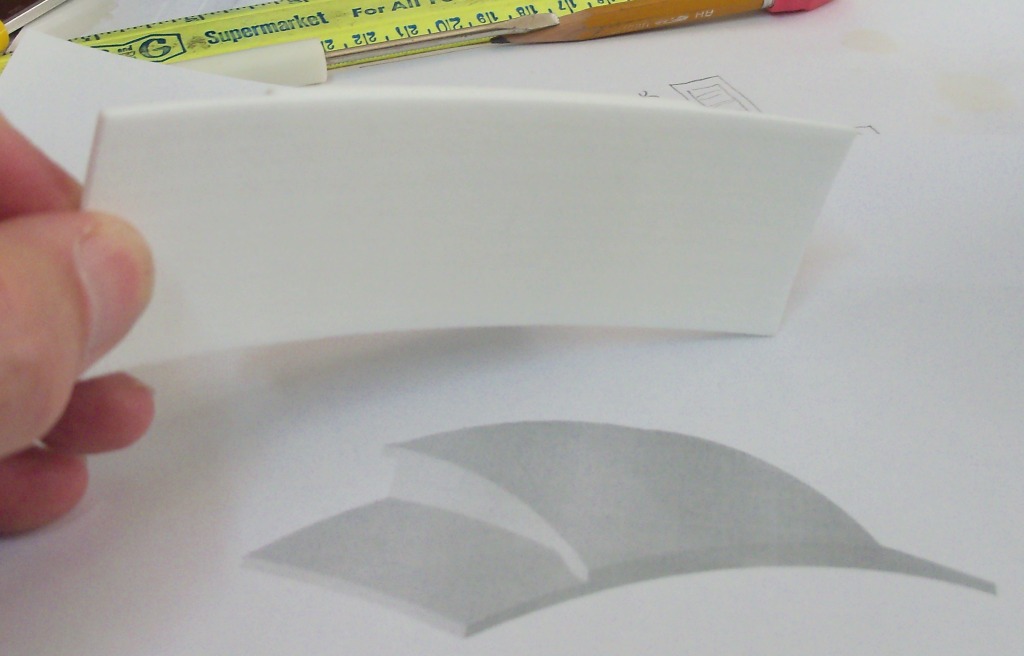
First and foremost, I am a novice with the 3D software. But, I'm learning. I think I mentioned that I would have two choices for the roof ends. Either I laser up parts in heavy styrene to glue together and putty, sand, putty, sand, etc, etc. And hope for a symmetrical looking end or I do my best to 3D one and get it printed. I opted for 3D'ing it. After 10 days of off and on struggling with drawing a compound curved roof with different ends I reached out to my old neighbor from California and his CAD friends. They also had issues with it. I hate giving up on something I know there is an answer to so I kept at it. Watching "how to" You Tubes and other tutorials with the program I'm using.
Finally, I read a procedure (obviously designed for a different application) that used a different drawing tool then I was using and got this.
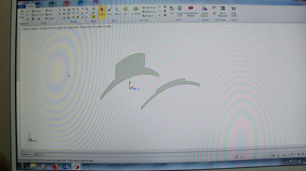
I drew up the back plan and the front with a 1.6" offset front to back and a drop of .2" to the front corners. The curve in the middle is .4" from bottom edges to top of curve.
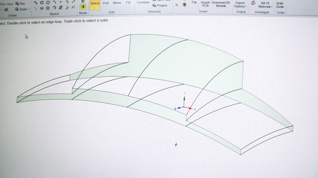
Then I drew connecting lines from the back to the front. 12 of them. Each line has to have exactly the same angle as the opposite side line. In this procedure, they are called trajectory lines.
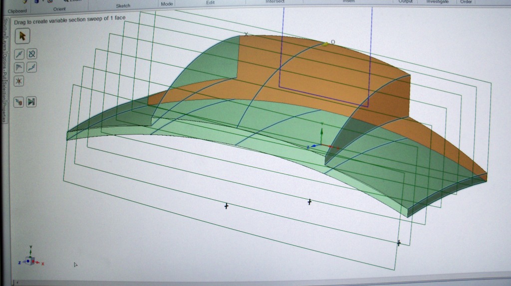
Then I pulled the back profile following the trajectory lines to the front profile and got this. And a great big smile on my face!!!!
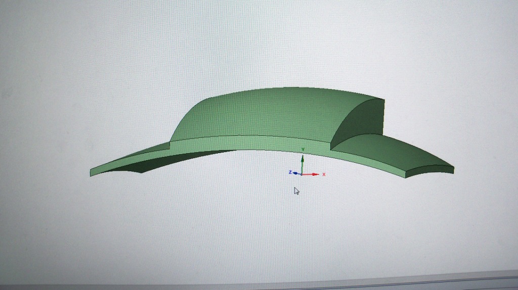
Did I save this image in a big hurry!!
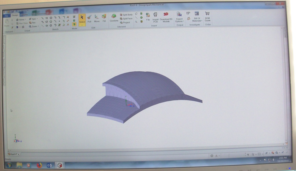
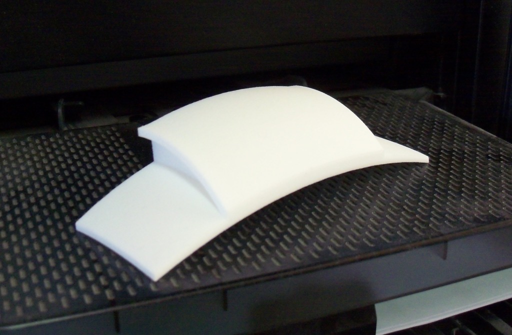
Then I added the trim on each side of the clerestory to get this. From here, I saved it as an .stl file which is one of several 3D file formats Shapeways will accept. I uploaded it to Shapeways and 1 week later received this in the mail.
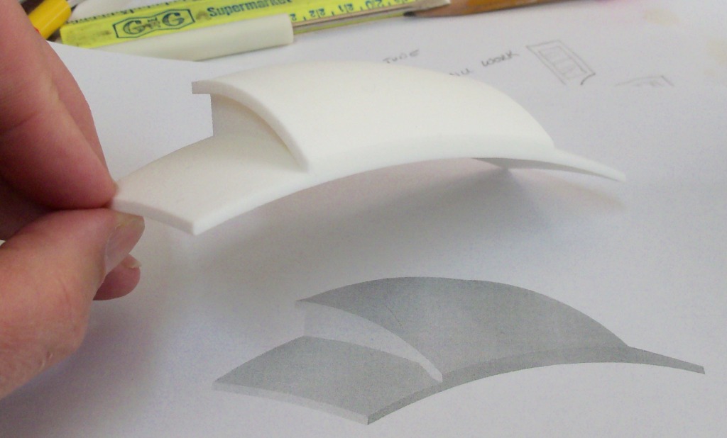
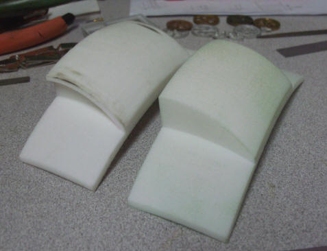
I'm sure others have done this and think, no big deal. For me this was the "crème-de-la-crème". Here's a few comparison pictures of the roof end Bob Hartford designed and had printed many years ago. The print was used to cast 2 part resin ends, now sold by Ozark.
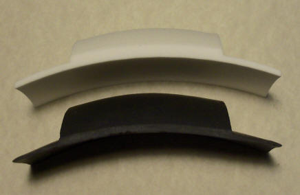
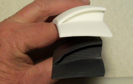
Front profile and right side profile. As usual, PNG parts are built a tad heavier.
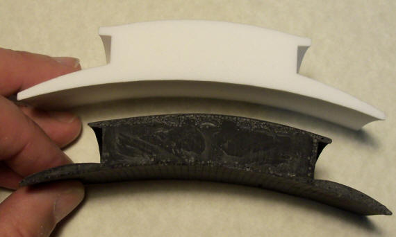
Here's the big thing I did when designing mine. Notice how thin the the roof is at the junction with the clerestory on the Hartford end. These ends typically arrive broken in shipment. This end was given to me by a friend. On the Hartford end, the roof is .1" thick. On mine, I made the thickness .1" at the edges and .250" at the clerestory edge. This tiny change will make all out lives better during assembly of the kit. And, as typical with a PNG kit, more robust.
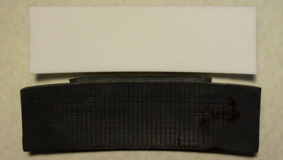
This is the bottom view. If I was willing to spend $2500 a year to lease Solidworks CAD software, I could have grooved the bottom to represent T&G planking. I'm using a freeware software so concessions have to be made. To get around this, I bought .010" styrene strips which I will glue to the bottom of my print to represent the planking. The strips cost me $3.00. Well worth the compromise!!!
Watch for the next update. I expect the next shipment from Shapeways Tuesday. It is the final shipment of the chair masters so I can start vulcanizing molds.
More "show & tell" to follow! Stay Tuned! Phil
Oct 25, 2018
I received the last of the chair masters. Remember I wanted them in a material that would withstand vulcanizing so I had them printed in steel. I did change the feet of the chair end. I had a little feedback on them thinking that maybe a foot plate would be easier when gluing them to the floor of the car. I agreed and modified the 3D CAD drawing and had Shapeways print 9 for masters. 9 is half the number needed for a coach so 2 spins will cast enough for one coach.
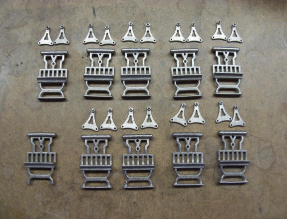
I need 2 rocker arms per seat so I had 18 rockers made. I drilled out the 2 mounting holes on the rockers to make sure the brads will fit and also milled out the holes in the chair ends for the rocker pin to pivots in. That hole is just below the arm rest. The lower left chair end is the original "test" print to determine if printing in steel was a viable choice. Lost wax brass was my second choice but easily twice as much money to print.
I also glued .010" thick by .125" styrene strips to the bottom of the roof end print to represent T&G planking.
All for now. Mold making is next. Phil
October 31, 2018
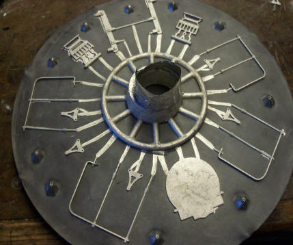
I started the mold making / vulcanizing process this past weekend. Got 4 molds made.
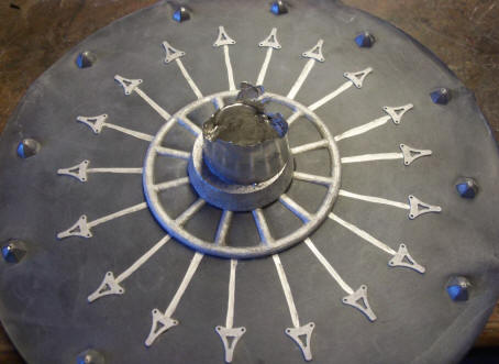
9 chair ends and 9 rocker arms laid out inside the steel ring. The outer acorn nuts are for indexing the top and bottom halfs.
The top attached to the top steel with my home brewed gating device. This helps distribute the molten alloy away from the core and develop greater centrifugal force as it reaches the sprues and ultimately the cavity to fill. Most casters do not use this method. I found it works for me so it's cavity is found in the hundreds of molds I've vulcanized.
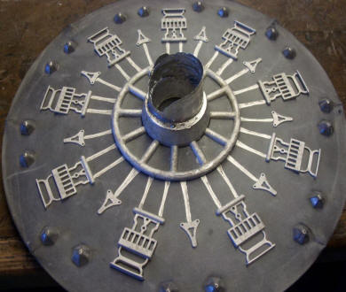
Fresh out of the vulcanizer and removed from the steel ring, top and bottom.
Close up. Parts still 100% intact!! However Shapeways make that steel, it is one hard material. AND .... great for a reusable spin casting pattern.
Even closer. Notice the bronze dust left behind. Bronze is infused with the stainless steel during the curing process at Shapeways. The first few spins with white metal will pick up all this dust. I can just toss those parts back in the melting pot. The dust will float to the top and be removed with other slag.
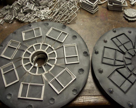
I made up 2 of the same mold. I need 18 seats per coach and for an additional $20 for the mold rubber, it's worth it for me as a production mold. You can see I've cut sprues from the gating device to the part cavities on the bottoms. Once in a while, I need to also cut a matching sprue in the top. Won't know until I spin the molds.
Close up of this mold. I put a fresh blade in my #11 exacto knife to cut these and toss it after completion. The hard rubber, as hard as a car tire, really dulls the blade.
Mold #3. 18 seat rocker arms with sprues cut.
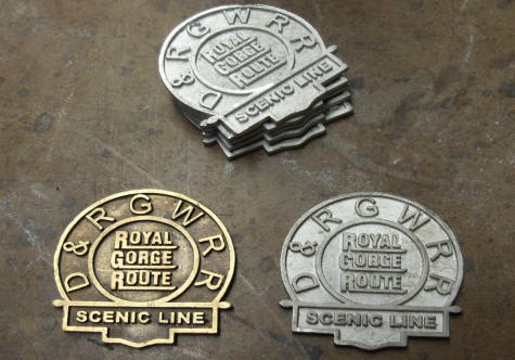
Mold #4 with handrails, a few chair parts and a D&RGW herald that's a lost wax brass casting I had made.
Close up of the herald casting on the left. On the right is a frosted detail piece from Shapeways. When I was building the destroyer, I asked the designer I was working with for weapons if he could turn a 2D drawing I had into a 3D. He agreed. This part is available at Shapeways in his store. Here's the link.
https://www.shapeways.com/product/JLR7JHKMJ/railroad-sign-set-of-4?optionId=42285109&li=marketplace
$12.97 for 4 plus shipping. FYI, I get nothing if you order a set. 3D Boats does. I had to enlarge the piece as the dimensions of the original didn't fit the criteria for lost wax casting. I also had to change the font of the lettering. Again for size issues.
All for now. Next update will be spin casting these molds. I'm having a few issues with the window masters. Hopefully I'll have that resolved soon as well. Phil
November 4th, 2018
I spent the day yesterday spinning the new molds. Once in a while, one will work perfectly with every cavity filling. Not so yesterday. Many of the parts are complex requiring extra sprues or wider entry ports to the cavity. Took 4-5 spins to get all the molds to fill properly.
Left is the chair rocker arms and right is one of the 2 combo chair end and rocker arms.
Left is the handrails, brake lever, a couple chair parts and the D&RGW Herald. Right is the windows. I still need to make 1 or 2 more of these.
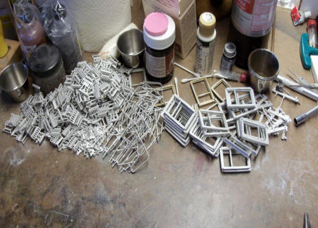
Left is a pile of castings and right the D&RGW Herald. Will probably throw this up on the parts page as a for sale item.
Final thing for this update is the mold of the roof end. I poured the silicone rubber yesterday and 24 hours later, today, got this.
I used almost 24 ounces of rubber for this $$ ouch!!! All for now, Phil
November 23, 2018 Update
I've cast 15 or so roof ends from the above mold. Lookin good for the first 10-12 and then I noticed a little pink silicone in the corner where the roof trim meets the front of the roof. This being caused by the trim to roof joint being a severe undercut. Every time a little rubber came out, the next casting had more material in that joint needing a s sharp knife to cut it out. So ....... I went back to my 3D drawing and removed the trim as it can be added later with laser cut wood. Doing so will create a smoother mold that should pop out the castings with no issues. Here's a comparison of the first and second 3D print.
I don't have enough silicone rubber on hand to make another mold so will need to make a trip to Denver to purchase more. No way am I going up there over Thanksgiving weekend, black Friday, etc. Tuesday or Wednesday of next week if time permits. But, I needed to work out all the laser geometry to cut the wood parts to make the roof. The existing roof end won't hamper that. Above you saw the mockup for the chairs. Well, here's the mockup for the roof.
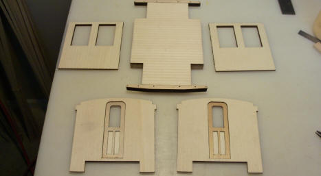
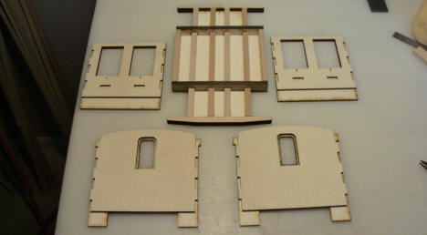
Front and back side of the walls. 2 layers with the inner layer being finger jointed for better assembly.
A piece of 1/16" birch glued to the resin casting on the left and piece of 1/8" poplar glued to the birch. The offset is 1/8" for the 1/8" balsa roof.
Front view of the casting, left and more poplar added on the right.
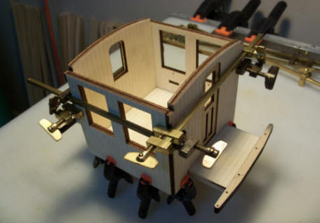
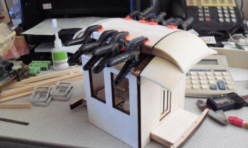
The added pieces create the "sleeve" to fit over the double layer car ends. On the right, the sides and ends glued together and clamped.
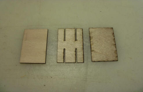
Clamps on the bottom side left and cutting the 3 pieces to form the seat backs for the chairs. The center piece is for the rocker to nail to the back once all three pieces are glued together.
You can see the 2 holes in the edge of the seat in the left picture. Placing the rocker on the seat back and driving the brads in.
Seat back with rockers left and seat ends with seat bottoms right.
Seats and roof ends in place. The seats are glued in but not the roof ends. I will place a sheet of sandwich wrap over the edges when assembling the roof so it doesn't get glued down.
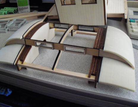
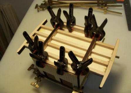
The only difference between this mockup and the full size car will be the number of carlins. Roof on and off the car body.
Gluing the center piece of balsa to the ends and carlin. I'm using balsa for the ease of bending it and the thickness to match the roof trim.
I'm satisfied with the look of the roof. a little short but this is just a mockup to get the cuts and angles correct.
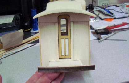
Car end and bottom side of the roof.
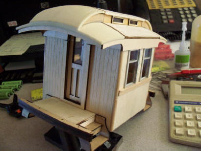
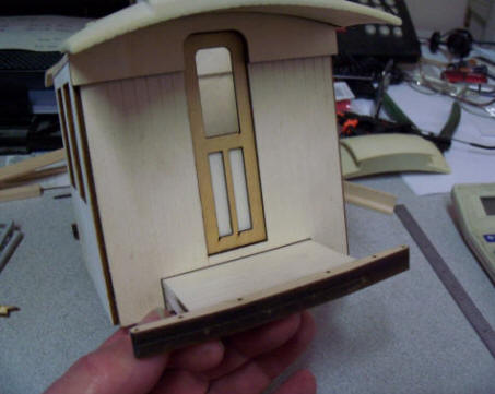
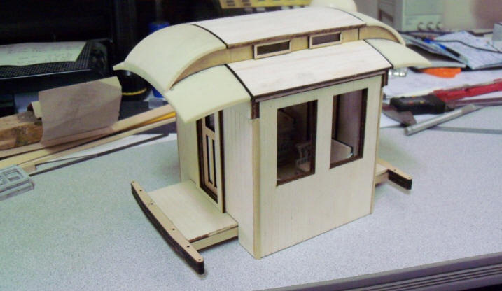
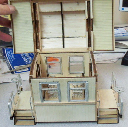
Inside and outside with steps, windows and trim. Still have the handrails and a few other goodies to apply.
All for now. More in the next week or two. Next mockup will be the full size car. Phil
November 24, 2018 Really, really short update!!
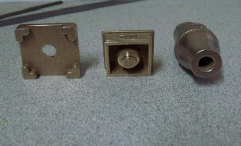
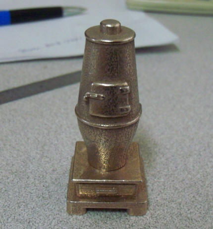
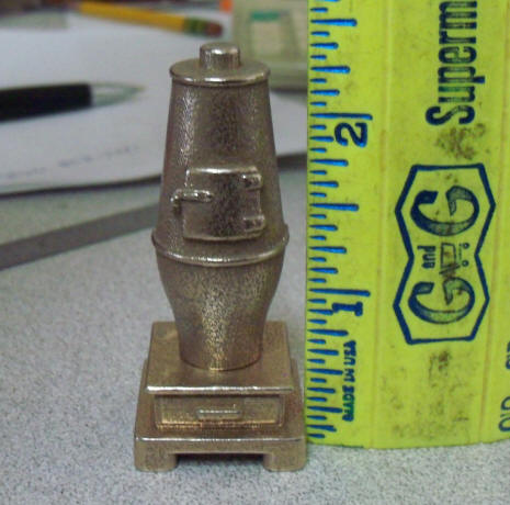
I received another batch of parts from Shapeways. I drew up a coal fired stove for the cars. Had to make it in 3 parts so I could vulcanize it. Rubber mold halves are 1/2" thick. Max safe thickness of a pattern is 3/4". Anyway, here's the parts and stacked up.
I had hoped to have the coach in production before Christmas but I'm not going to rush a single part. It's now looking more like January.
More next time. Phil
November 29, 2018
I finished up the 2nd mockup for testing the roof components. I made up a few more "in shop" brass patterns like truss rod NBW's, stove exhaust, vents and bathroom vent.
End view with railing, NBW's and brake staff, lock pawl and wheel. on the left and a side view on the right. A new lock pawl and brake wheel are still getting printed at Shapeways. My "old trusty" brake wheel was cut on a CNC mill almost 20 years ago. I 3D'd a new one with more detail, still robust, but in 2 flavors. One standard with a hole for mounting in the middle and the other with a square block out the bottom. With this, we can drill a hole for the brake staff in the block 90 degree from the wheel plane so it can be mounted at a 90 angle as the real cars stowed them when "underway".
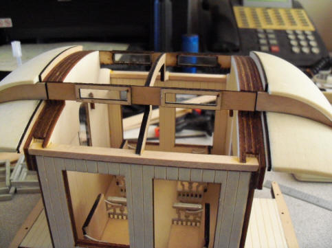
Bathroom vent lower left, roof vents middle and stove vent upper right in the left picture. Roof off and tilted back in the right picture.
Looking into the car (less stove and bathroom) on the left and the bottom side of the roof on the right.
All for this update. The bathroom parts should arrive Denver tomorrow and Falcon Saturday. The lock pawl and brake wheels are still getting made. I'll post pictures of those parts as they arrive. I have a few task to work on over the next couple of days and then will get started on the first full size coach. For sure, I'll find a few more things to "fix" before starting full blown production. Phil
12-09-2018 Update
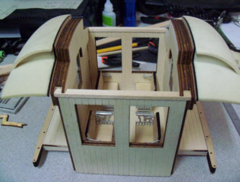
Every time I think I'm ready to tackle the full size car, I get comments or questions about a particular part or section of the car. Latest one was the interior sides of the car. The first mockup was to test the chairs. The insides were totally raw wood. I chewed on that for sometime and decided to make a minimal paneling and chair rail. So here's what I came up with. The paneling is 1/32" birch plywood and the chair rail is 3/16" by 1/16" basswood strip.
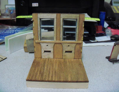
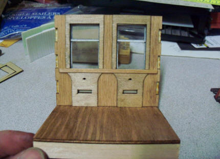
I painted on a little cherry stain to rid the raw wood look.
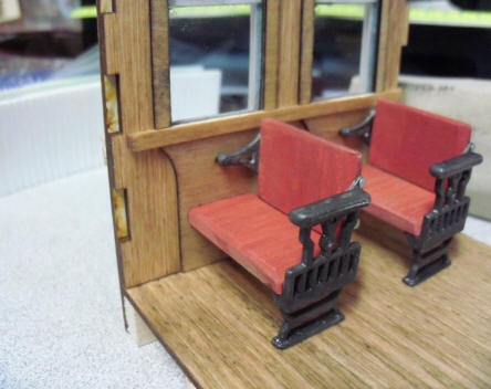
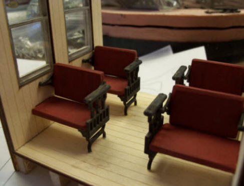
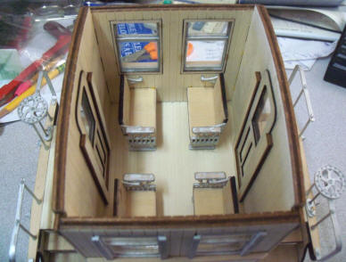
With chairs. I think this is a good representation of an interior without earmarking it as a specific railroad.
I'm working on a second roof for the roof mockup car. I received concerns that the balsa roof sections were going to be way to soft for a "working" piece of rolling stock. My intent from the start was to cover the roof with "tar paper". Those that have built my MOW kits that included fabric to use as tar paper will understand that thought. It's a fabric used to make sewing patterns that I get from Joann's Fabric. The surface is painted with a diluted mix of white glue and water and the fabric applied followed by another coat of thicker glue/water mix. Once dry, it creates and hard shell that should seal and protect the balsa. I chose the balsa for it's ease in bending to the contour of the roof. More on that in the next update.
FYI, the last shipment from Shapeways with brass masters is in route. Should be here before the end of the week. I'll get the last spin casting molds made and tested by next weekend. I'm getting there, slowly but surely!! Phil
1-1-2019 Update
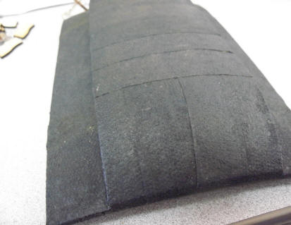
I made up 2 more mockup roofs to test gluing fabric onto the balsa wood to create a good hard shell surface and to blend in the cast resin ends and the balsa center. First up was my old standby called Pattern Ease. I buy it a Joann's Fabric buy the bolt. It's used to trace over commercial patterns that have multiple size markings so the size the seamstress can be copied without cutting up the pattern. I've been using it for tar paper roof for years.
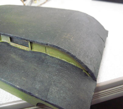
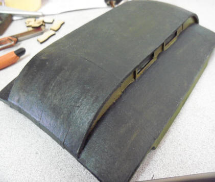
After the glue dried, I painted it with a grimy black and sprayed it with a matte rattle can finish. Above I had indicated a mix of white glue and water to dilute the glue a little. For this roof I found straight glue, I use TiteBond II, worked better than diluting it.
A good friend and I were talking about different materials to use as tar paper. He likes to use Kleenex brand hand towels. Those are sold in the paper isle of most supermarkets. I couldn't find Kleenex but did find Vanity Fair brand hand towels. Bought a box and gave it a try.
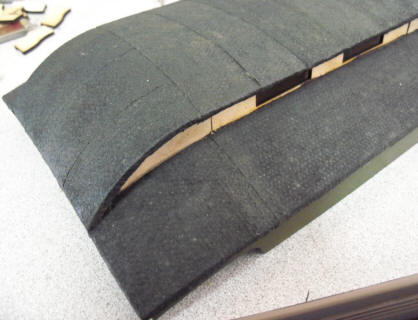
Hopefully you can see the difference. The hand towel left a bumpy texture that personally, I don't much care for. But I wanted to present that method as well as my trusty method. I will be supplying enough of the pattern ease with each kit to cover the roof. If you have your preferred method, by all means use it.
Hopefully you've noticed that I added 3 more buttons to the top of this page. Coach, Combine and Baggage. I have nothing more to add to this page so now it's time to follow the full size build for each car starting with the coach.