
700 Series Drop Bottom Gondolas
Don Winter
1942-2007
This page is dedicated to the memory of my friend Don Winter. While my methods of kit production do not match those of Don's or other manufacturers, I think one can get the idea of what's involved with bringing an idea to the table and packaging it for sale. Don produced a dozen or more kits in 1:20.3 scale over a 4 year period from 2001 through 2004. 25 years ago, he was a pioneer in the 1:24 kit production and before that, On3 kits. Those kits still pop up on e-bay from time to time.
My first customer "dollar" came from Don. He needed formed brass wire grab irons for his OV project and I was his supplier. That was in October, 2001. In May of 03, I flew to Orlando for a week to visit several laser shops. At the time, Don was living in Maitland, just north of Orlando. We spent several days visiting shops and discussing "technology" changes we both needed to continue our manufacturing businesses. By the end of the week our long distance telephone friendship had cemented into a more personal relationship.
There was no competition in our relationship. Neither one of us had a dog that was bigger than the other's. Just a deep understanding of the long hours spent cutting parts and developing affordable rolling stock kits. While my design is far different from Don's, I have preserved the "yoke" system we worked out late one March of 03 evening.
Phil
Update 1, 10-05-2007
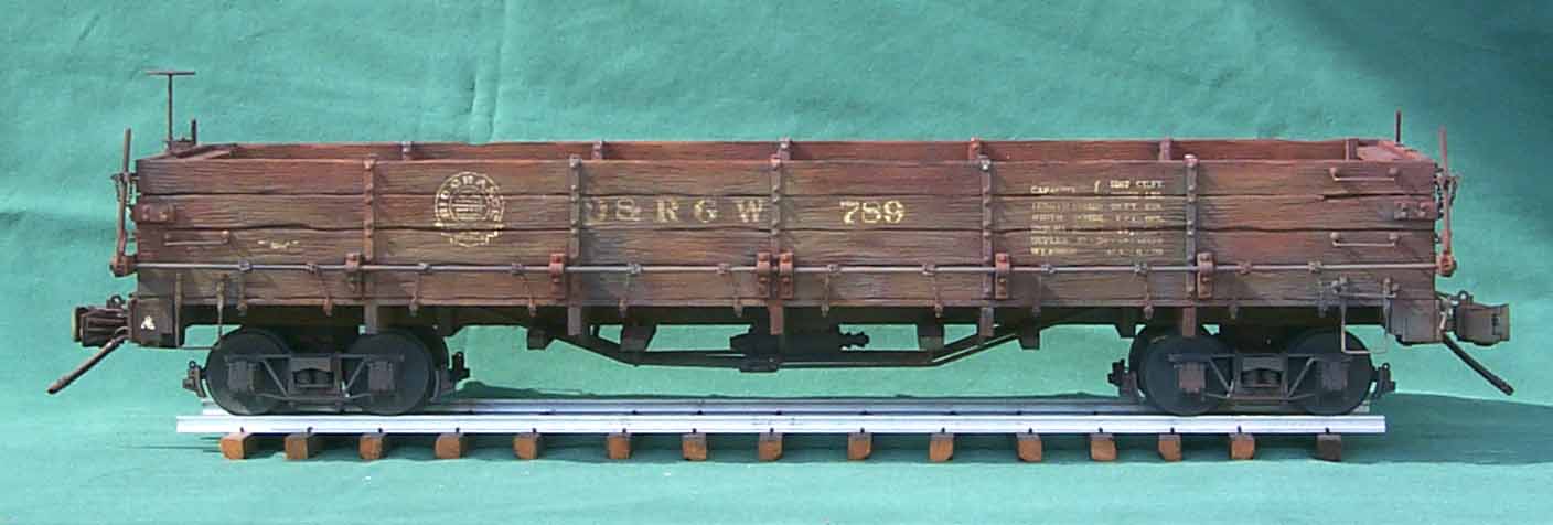
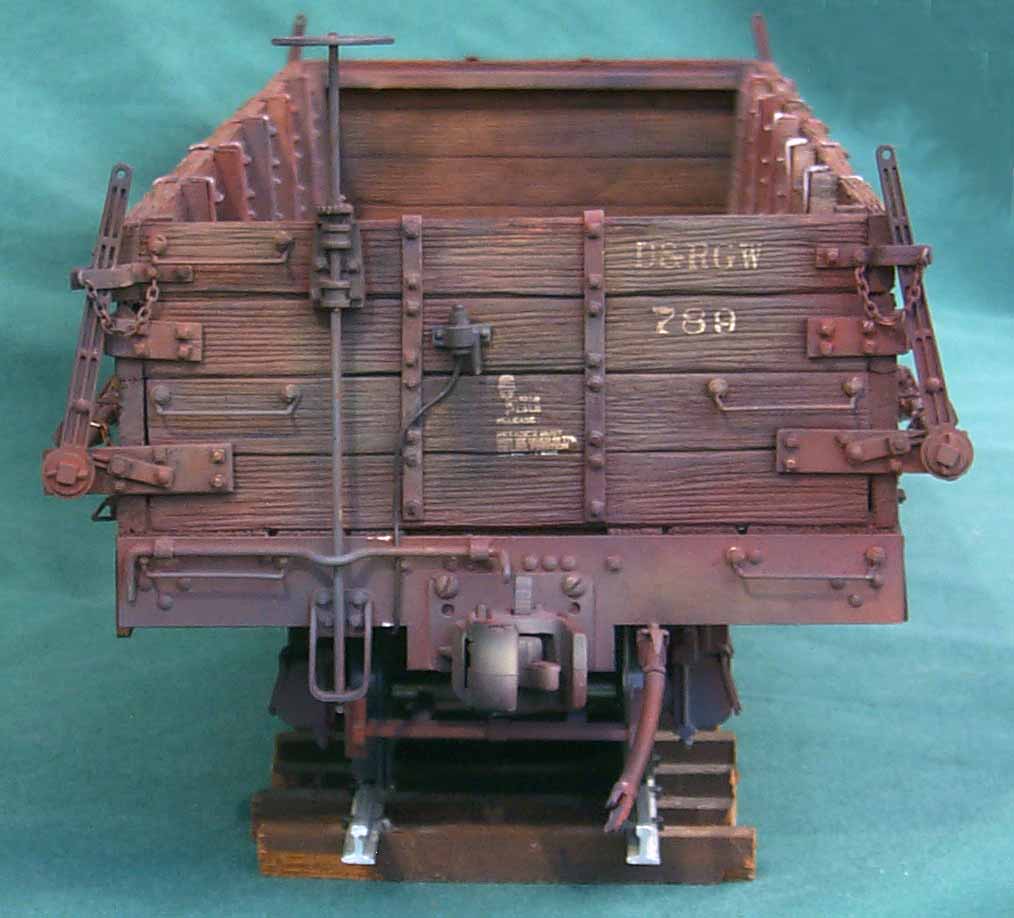
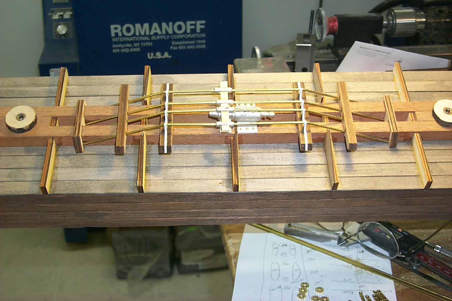
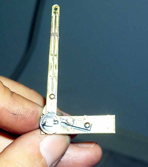
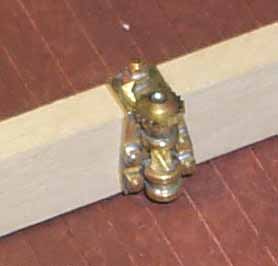
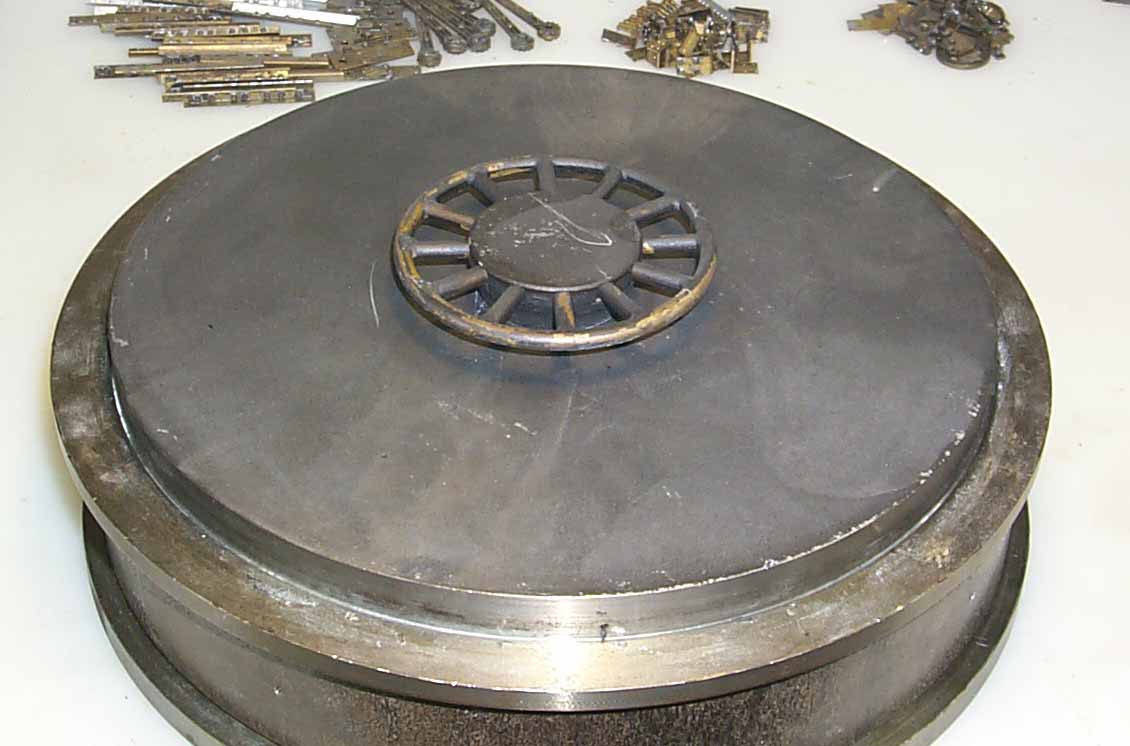
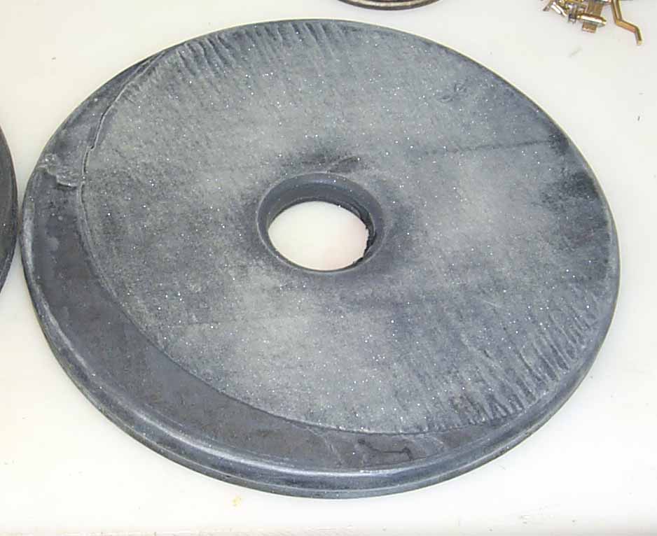
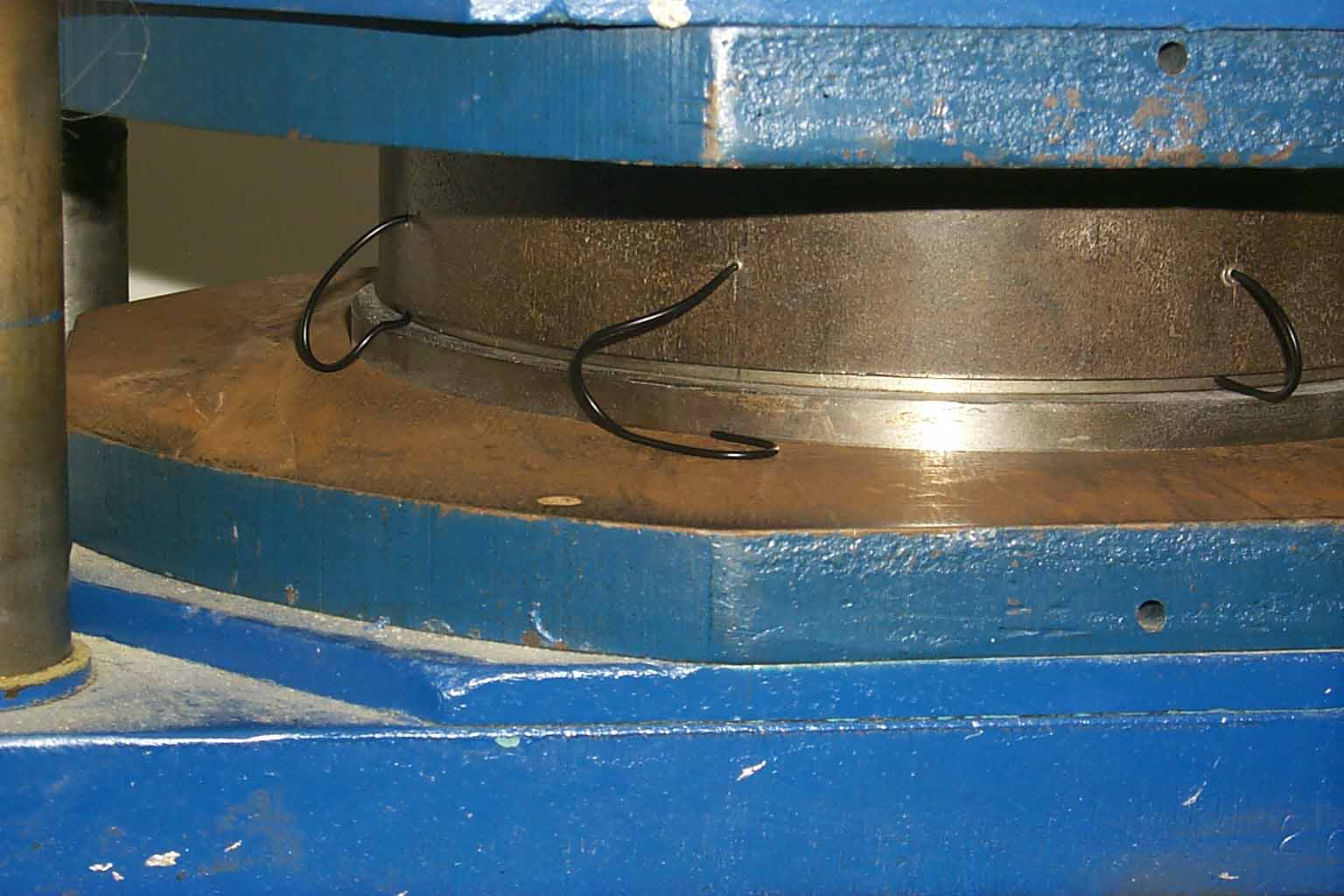
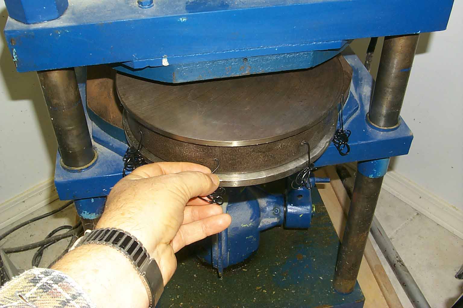
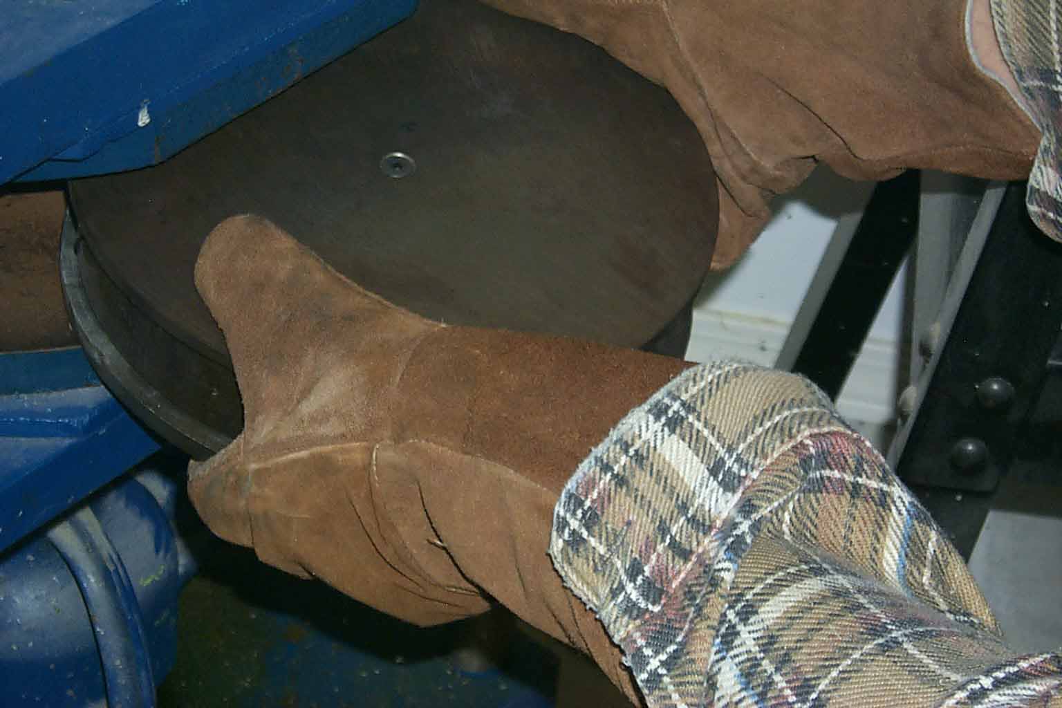
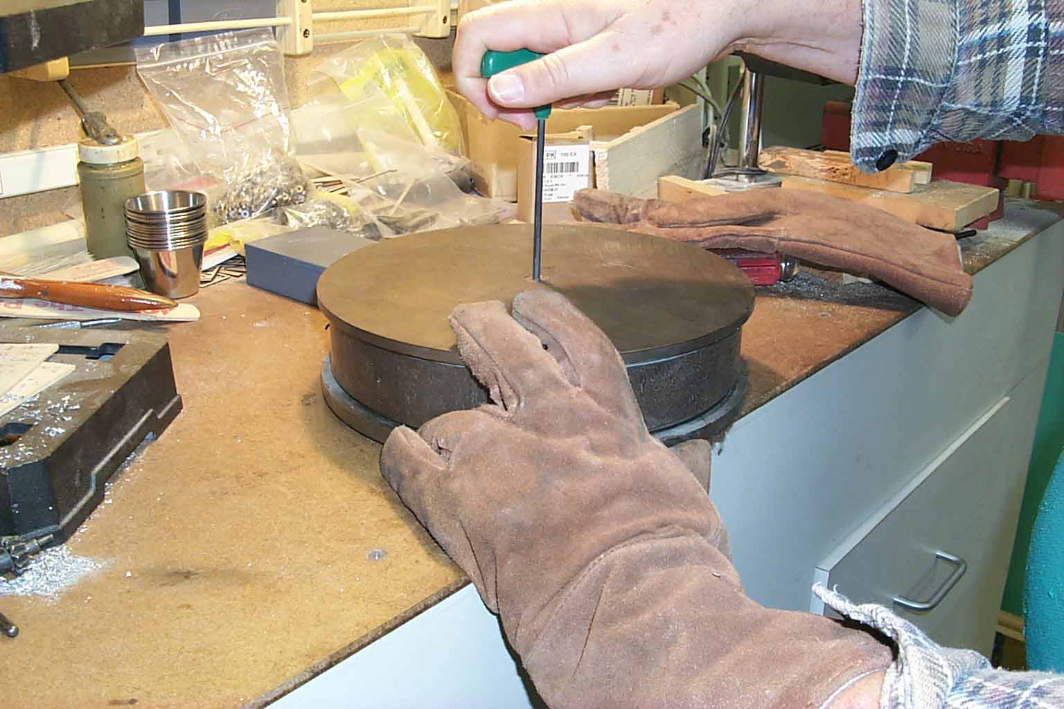
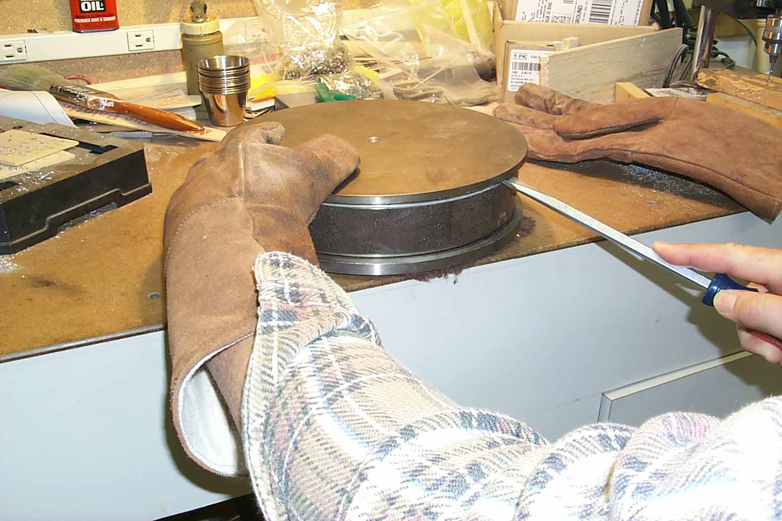
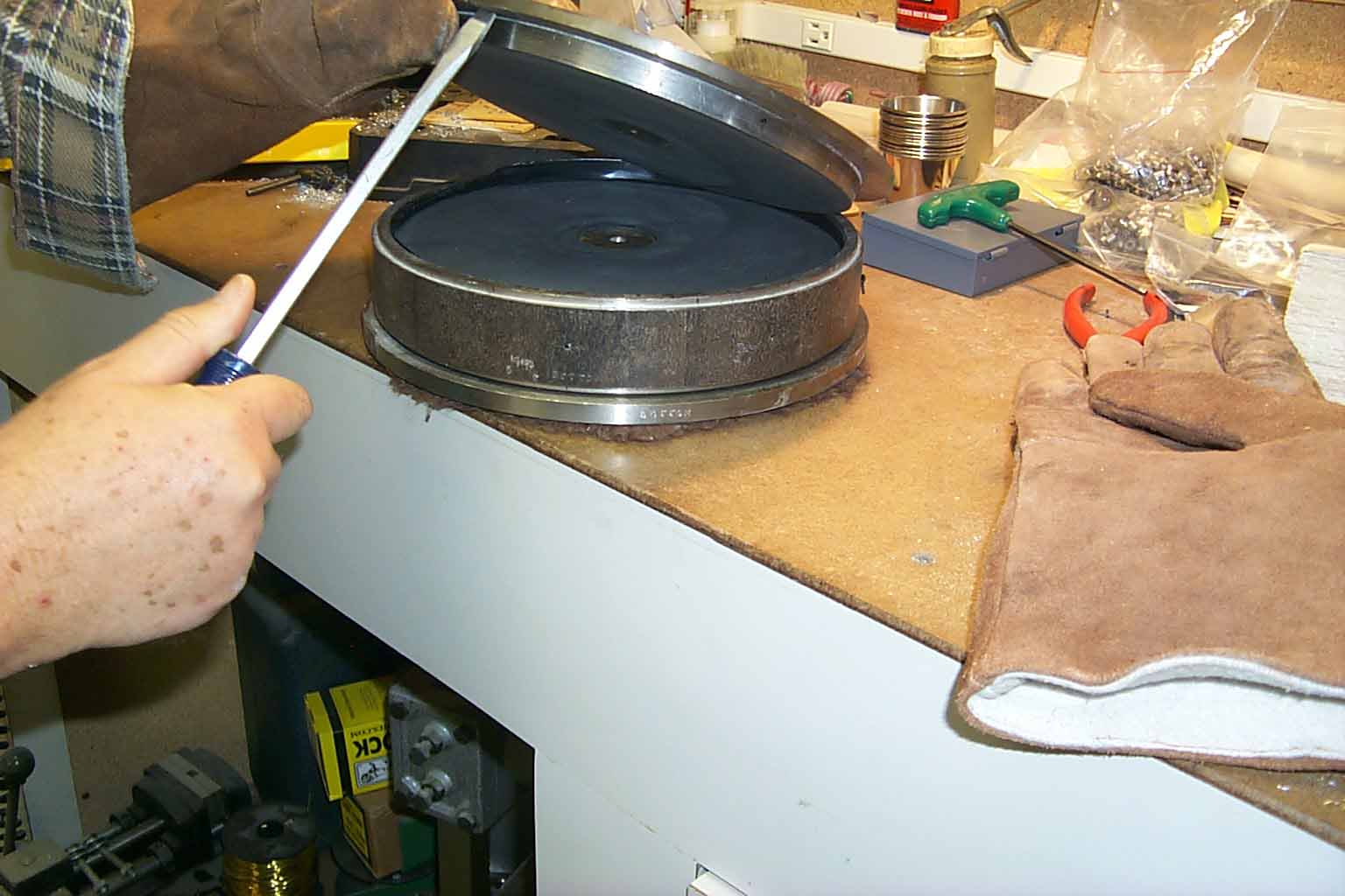
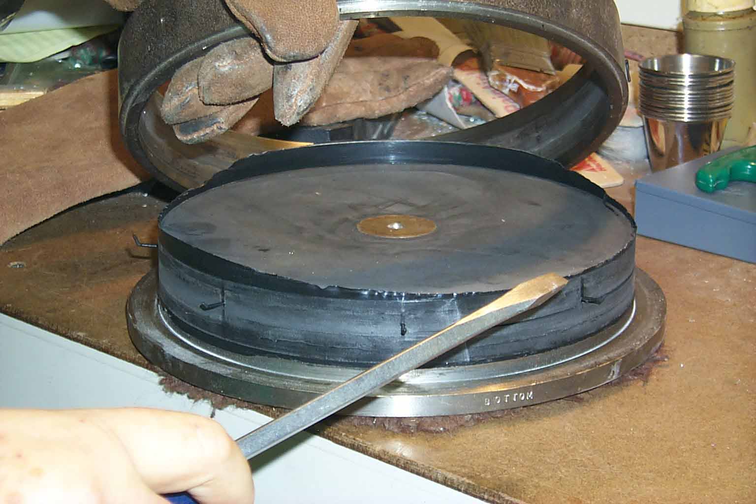
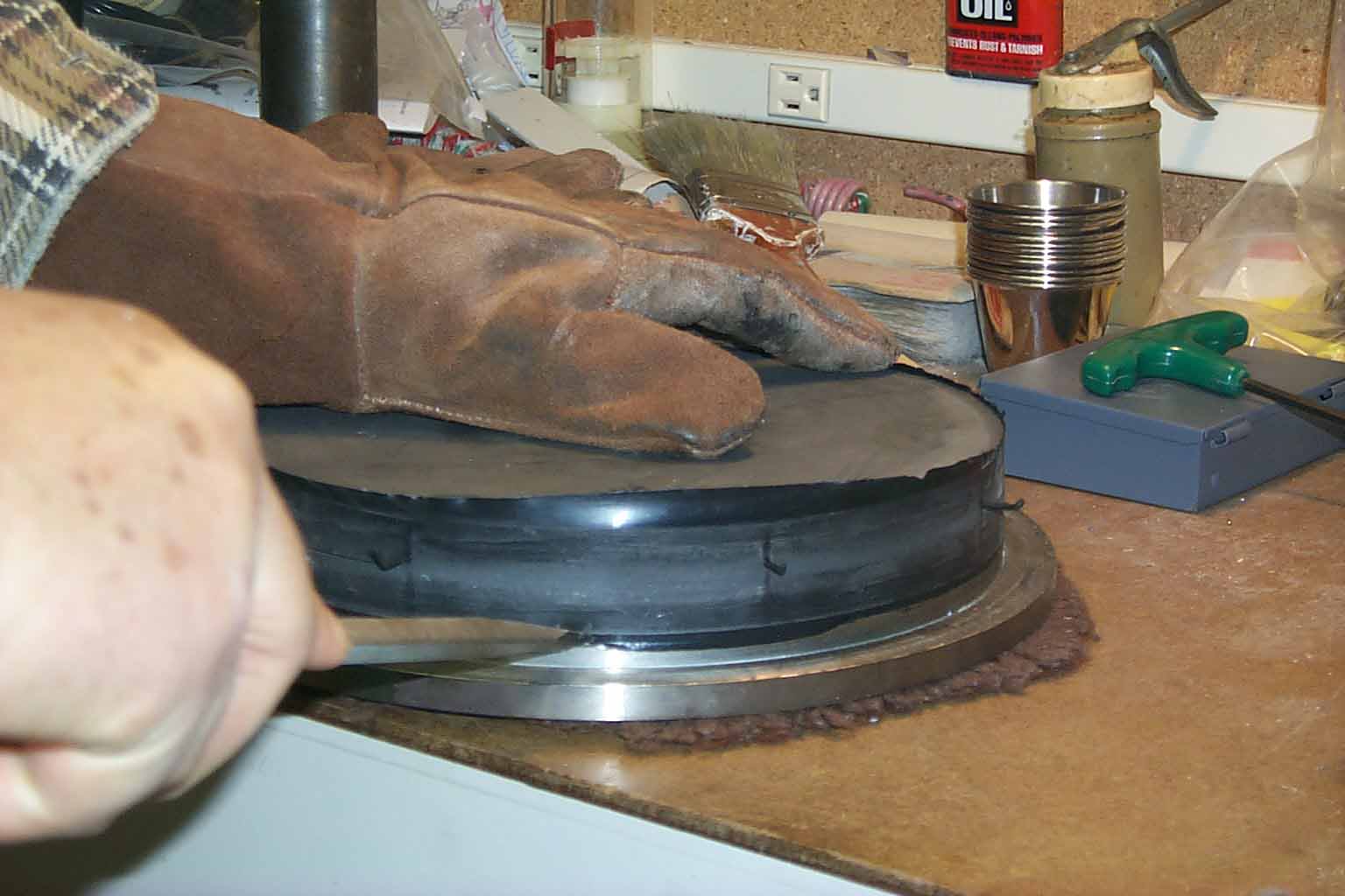
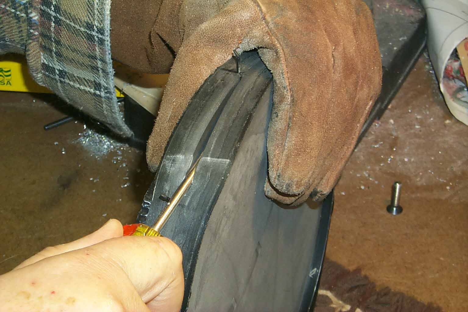
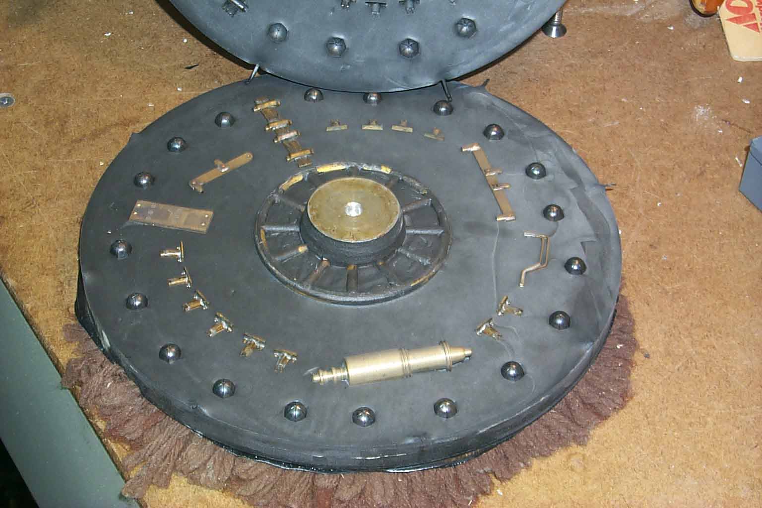
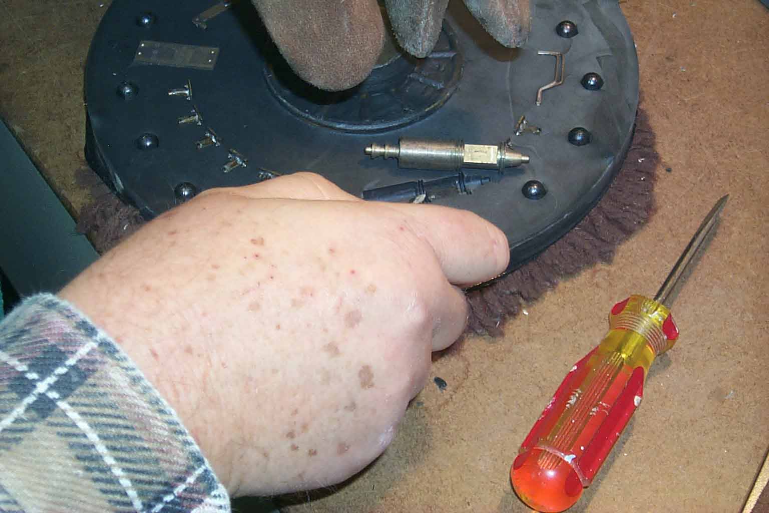
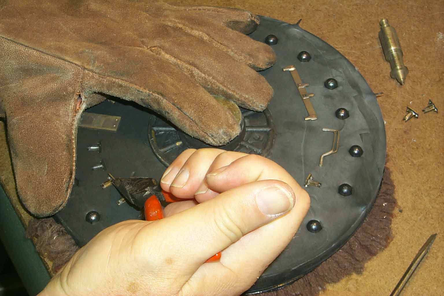
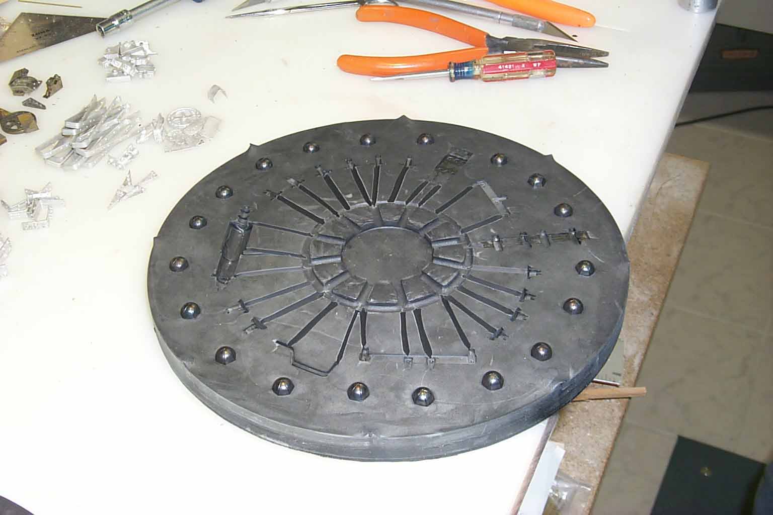
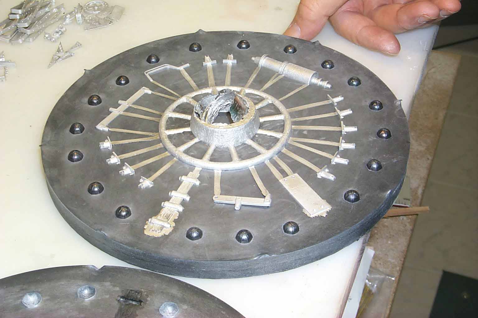
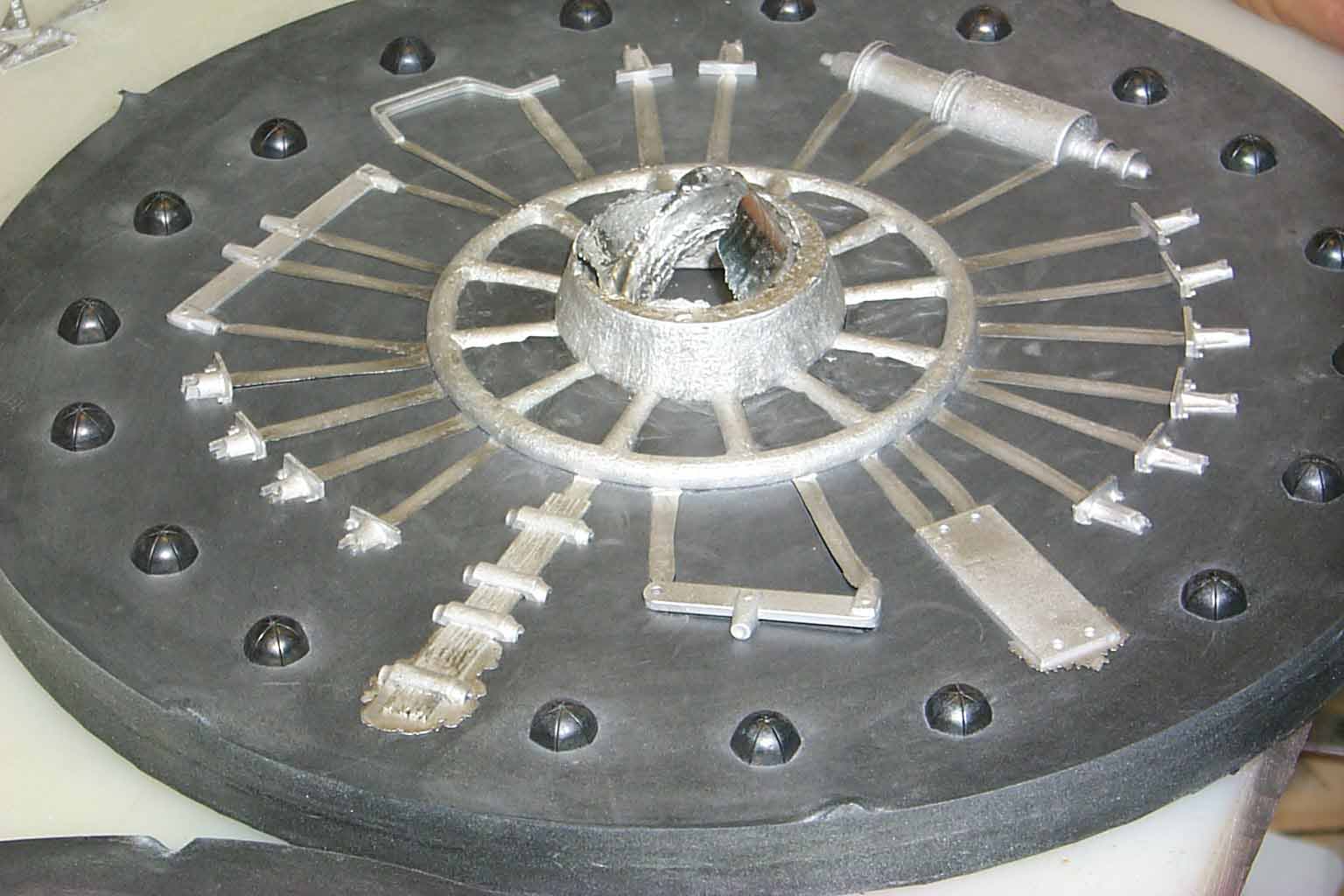
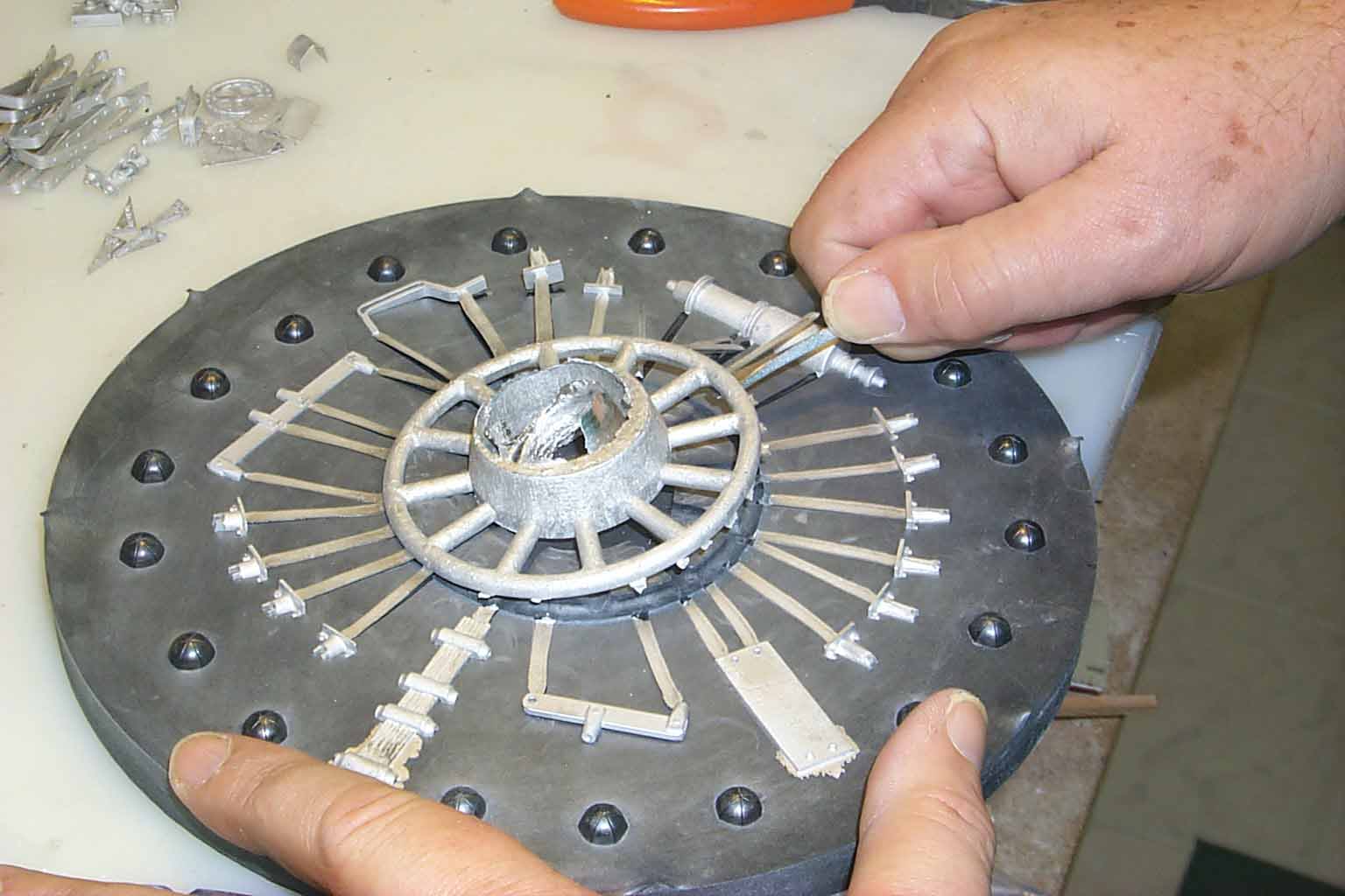
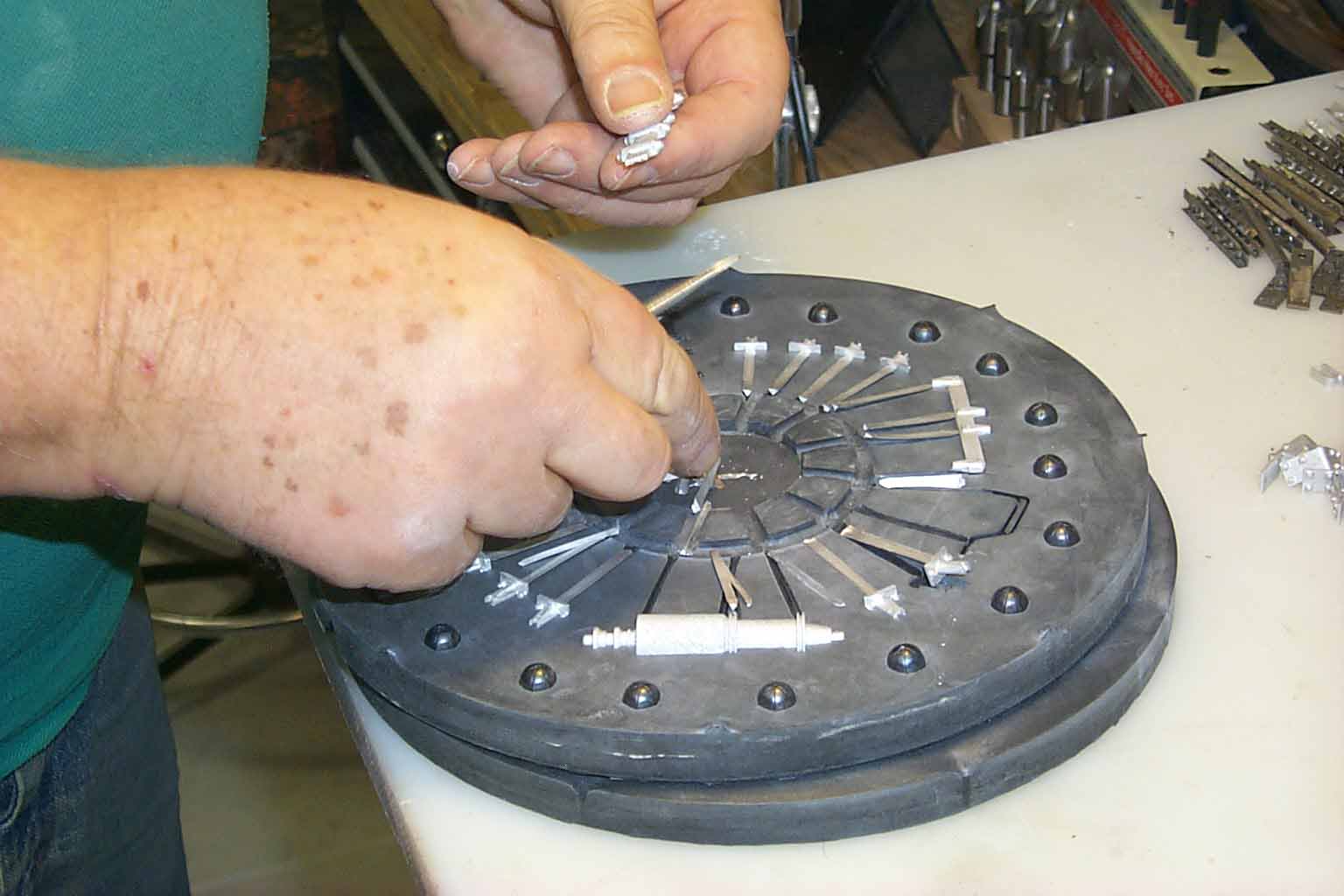
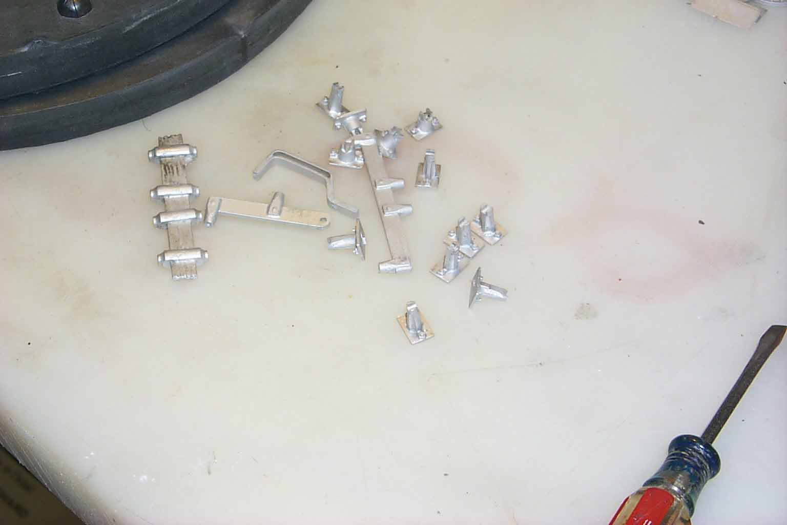
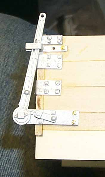
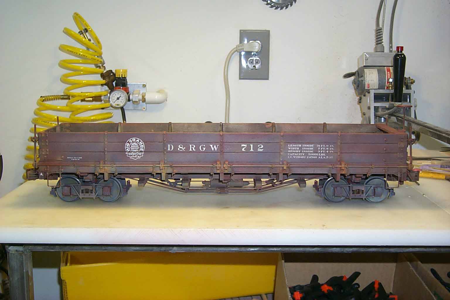
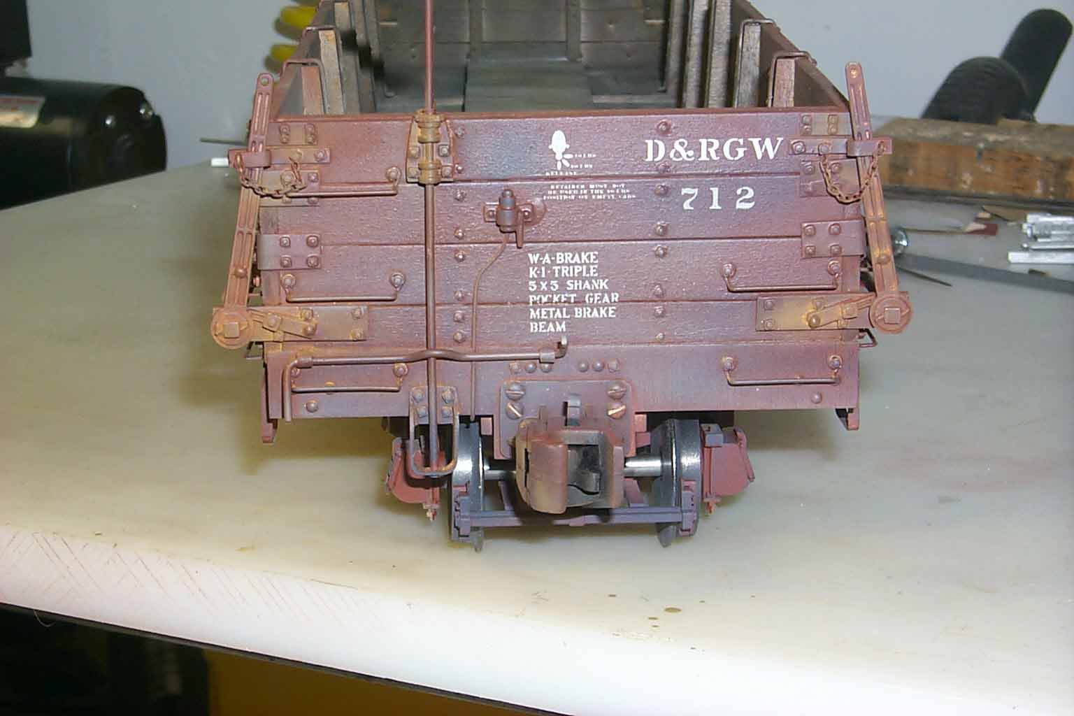
Hopefully, these 3 pictures are plenty to grab your interest. This will be a month long or longer input from me. Don Winter introduced this kit in the summer of 2003. This was one of his "budget" kits as he liked to refer to them. Let me also point out the handles and retainer on this model are not from Don's kit but from PNG casting of my making. More on that later.
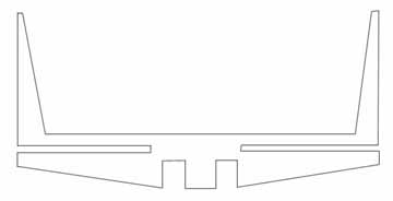
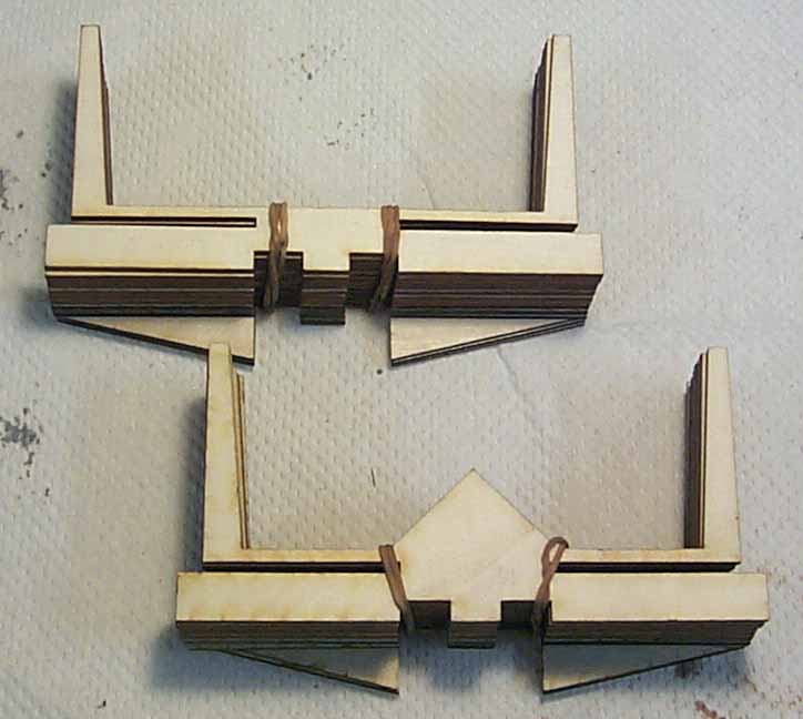
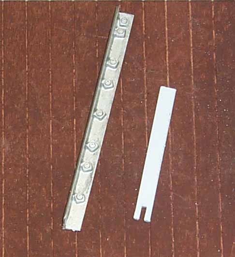
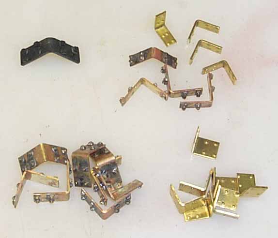
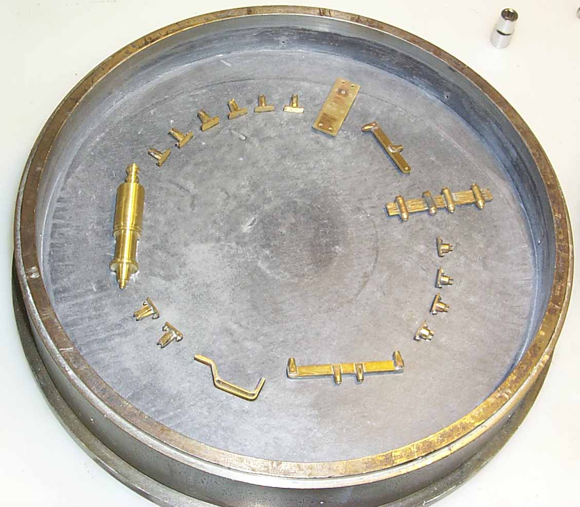
Don and I frequently shared the joy and misery of kit developing. When one was "stuck" on a problem, he would pick up the phone and call the other. Of course once the problem was resolved, we'd chat about everything else for an hour or two before hanging up. One evening in the spring of 03, Don called me with a show stopper for his DB kit (drop bottom). He needed a part that would hold the floor boards and provide the side post to glue the side boards on. It would also have to hold the center sills spaced to the proper width. He had tried several methods and all didn't work. Once I had a grasp of what he needed, I drew up a part Don coined as a "yoke". On the left is the actual drawing I e-mailed him. I slammed this together while we were talking. As you can see, it is a rough drawing and not symmetrical. On the right are the yokes as supplied in Don's kit. The bottom set of yokes build up the center hump car. I have one of these kits. Not sure how many of this version he made.
Besides the "yoke", Don asked me to make up longer versions of my strap steps which I gladly did. I supplied Don with grab irons, strap steps and nut bolts for this and other kits.
So....................... on with the show. The first step for me was to build up one of Don's kits. I do own a 3-Foot Classic DB and plenty of reference books. The best book in my library for this car is the 700 Series Drop Bottom Gondola Quick Pic Book by Rick Blanchard. I assemble all the wood parts, first distressing them with a Dremel tool and ganged up cut-off blades and dousing each piece with a 50/50 mix of India ink and alcohol.
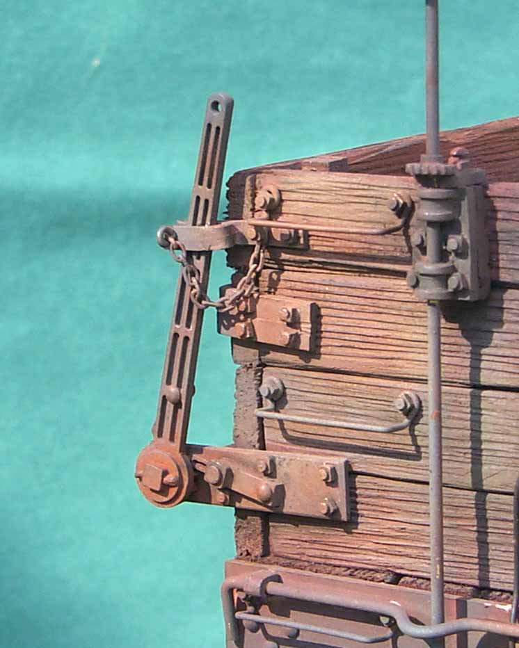
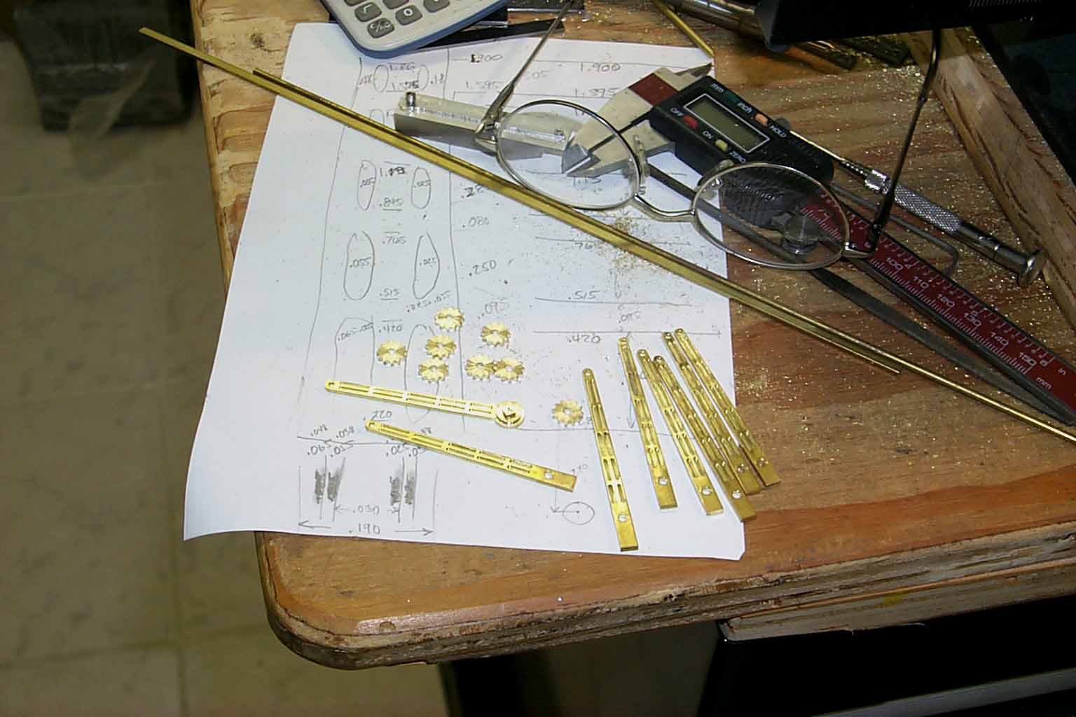
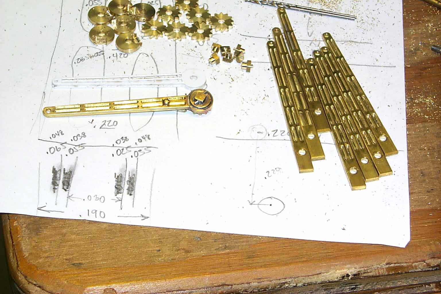
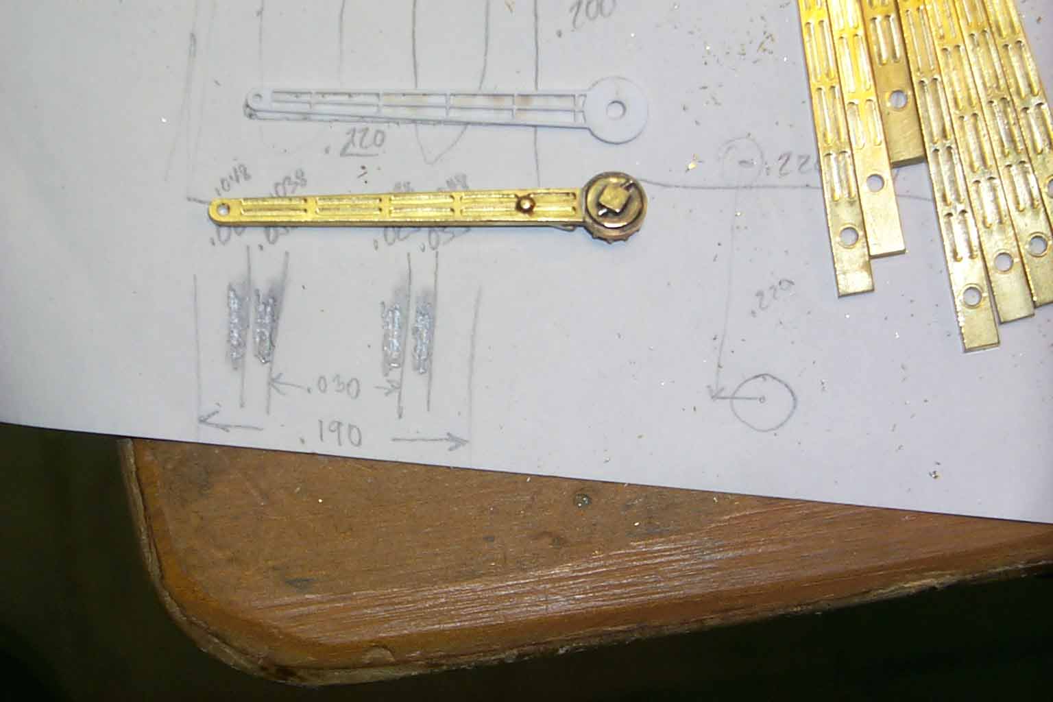
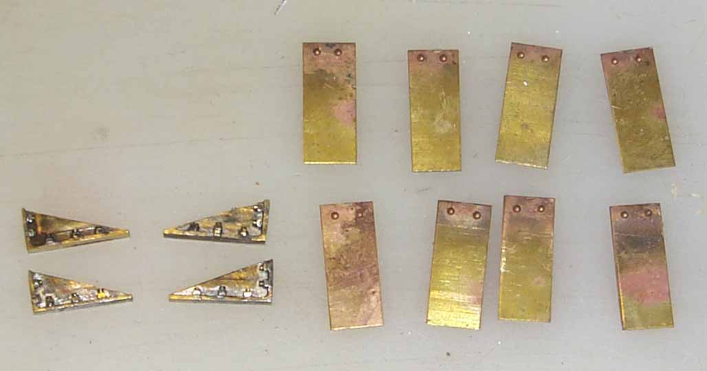
At this point, I was ready to add the white metal hardware to the sides and ends. I looked over Don's lasered plastic handles and knew this was a part that would to be updated. The following pictures are of the brass masters for the new handles. All manufactures have their own "madness" in the casting process and I'm sure my madness is different than others. I have found that the best cast parts come from cavities in the mold that were made by "original" masters. Not secondary castings or anything else. I also like to cast enough parts of a particular piece for 2 cars in each mold if possible. On the drop bottom, they're 2 left handle / lock pawl and 2 right handle / lock pawl. That meant cutting 4 sets of left hand handles and 4 sets of right hand handles. Very time consuming but also very rewarding when the parts come out of the spin casting mold. Here's the masters as I cut them. These are thumbnail pictures you can click on to blow up. Size does count!! Click your back button to return. A couple shots have Don's plastic handle next to my brass masters.
![]()
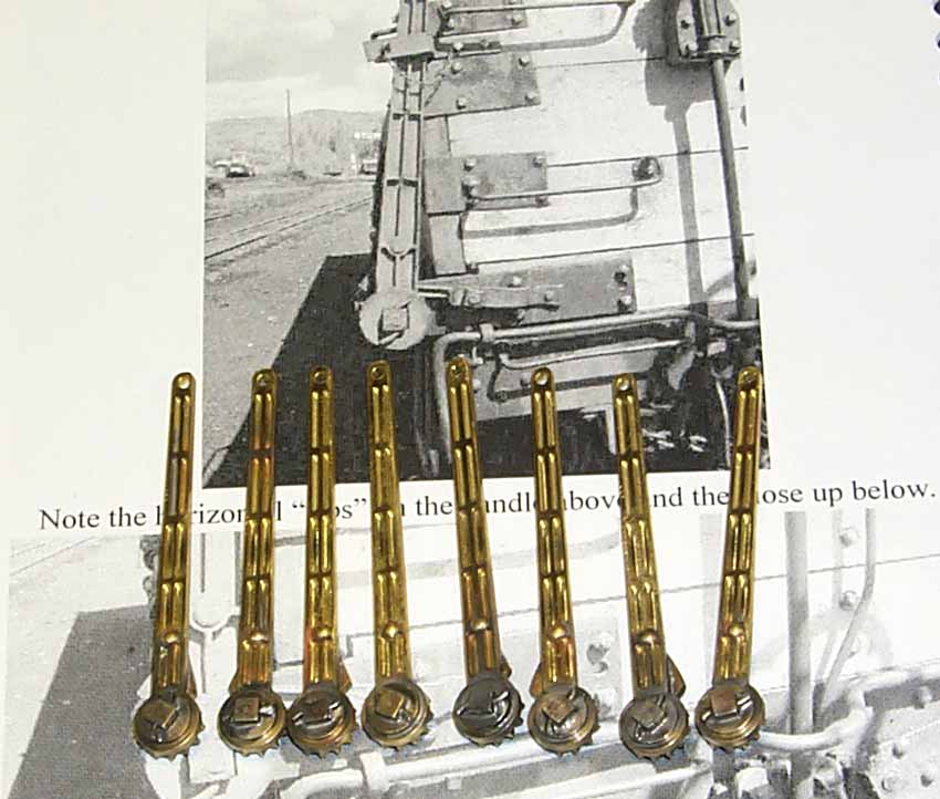
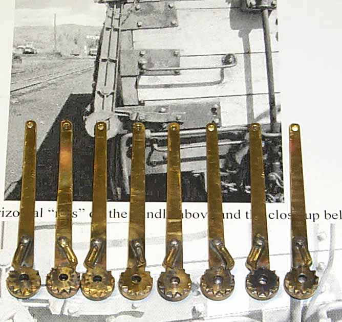
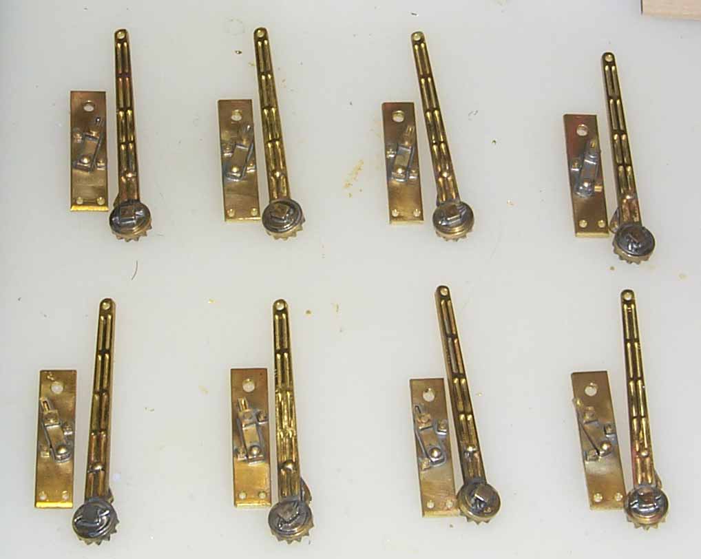
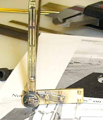
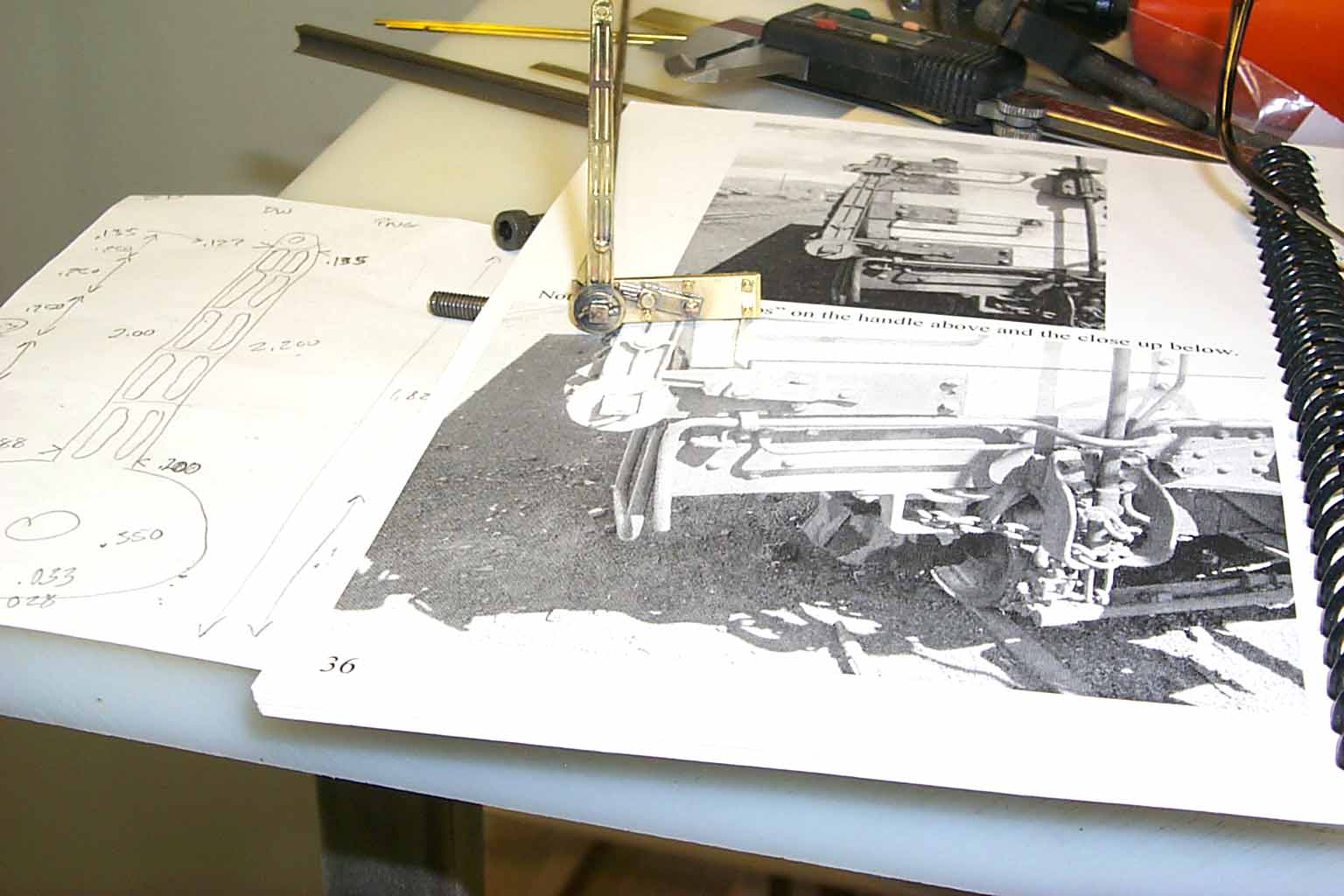
Several of these pictures were taken on my mill. Besides the calipers, I hope you noticed the high powered reading glasses. We all kid around about the 3 foot rule for detail but when making masters, it's really the 3 inch rule. The older I get, the stronger those glasses get!! Another point for you to ponder. The above parts took 50 hours of work to produce. Don't know where the other manufactures keep their masters but mine are at Fort Knox!!
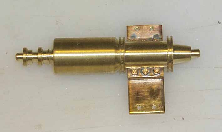
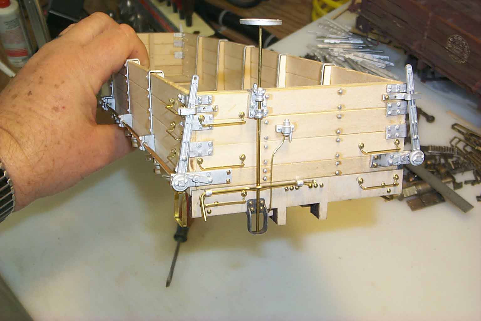
Once I had the masters, I vulcanized a mold and cast enough to finish Don's kit. The following shots are of the car with all the metal but before painting.
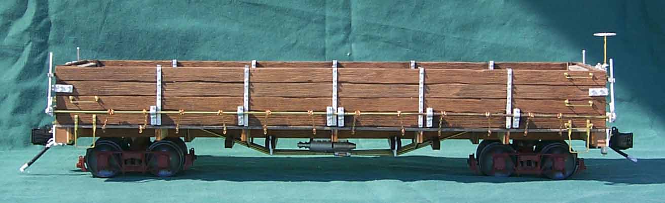
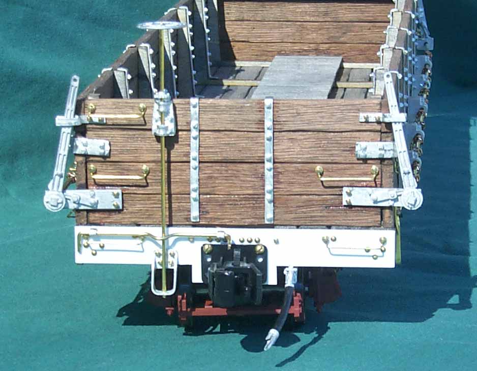
If you own or have built one of Don's DB kit's, you have also noted that the door chain brackets on this car are not the plastic parts but are lasered 1/16" birch plywood. Painting was next and those pictures are at the top of the page.
Well, that's it for now. The next step for me is to develop a frame jig and frame for the kit. Like all the rest of my kits, this one will have a pre-assembled frame to get you started with the construction. I will continue with side by side comparisons of Don's kit to the new PNG version.
Don did a marvelous job with this kit and it was very rewarding to see it come together. If I recall, he charged $65 for the kit less trucks and couplers. Not sure if he ever made a dime on this project but bringing a difficult car to market was far more important to Don than the bank statement at the end of the day. Pretty sure he told me that he made 140 DB kits to sell. If you own one, you own a very fine representation of a very unique car.
Send me any questions or comments and I'll add them to this page. Don wasn't just my friend and I know many of you have bits & pieces of information worth sharing.
See you next time.........................
Phil
Update 2, 10-23-2007
I've heard from a couple of you. I think the common thread was about Don's friendly nature and willingness to assist. The other common thread was whether I would make parts available separately from the kit to those wishing to upgrade parts on their Winter's kit. Yes, that is part of the plan. While Don left off some detail completely and used styrene parts as a quick fix on other parts, overall, it is really a nice addition to any railroad. My parts will fit Don's kit with a little fitting and increase the robustness and appearance of the overall model.
So, lets get on with planning and executing the kit. As a kit and scratch builder myself, I do not like to open a box full of uncut lumber and a set of difficult plans. I think this is one place PNG kits are very different from others. I prefer to have a basic frame built and square. I also like all the lumber cut to size. One or two pieces to be custom cut by the builder is acceptable but not the entire kit. Those that have built my kits know this to be a PNG standard. Decent instructions with plenty of pictures or illustrations is also a must.
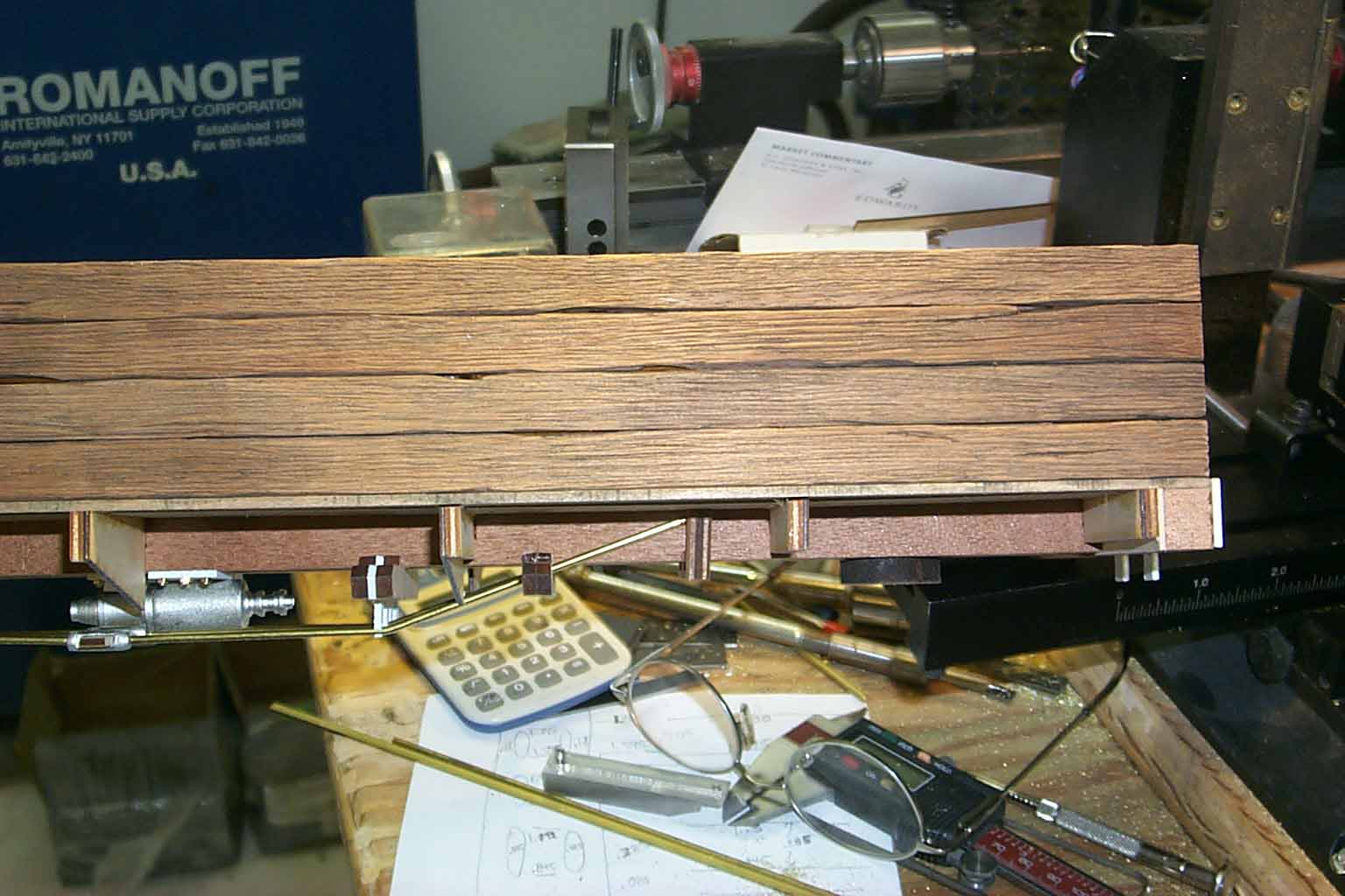
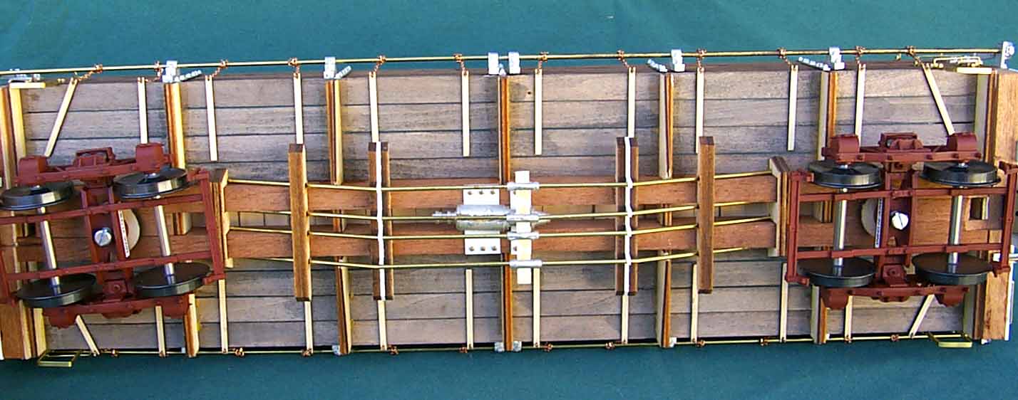
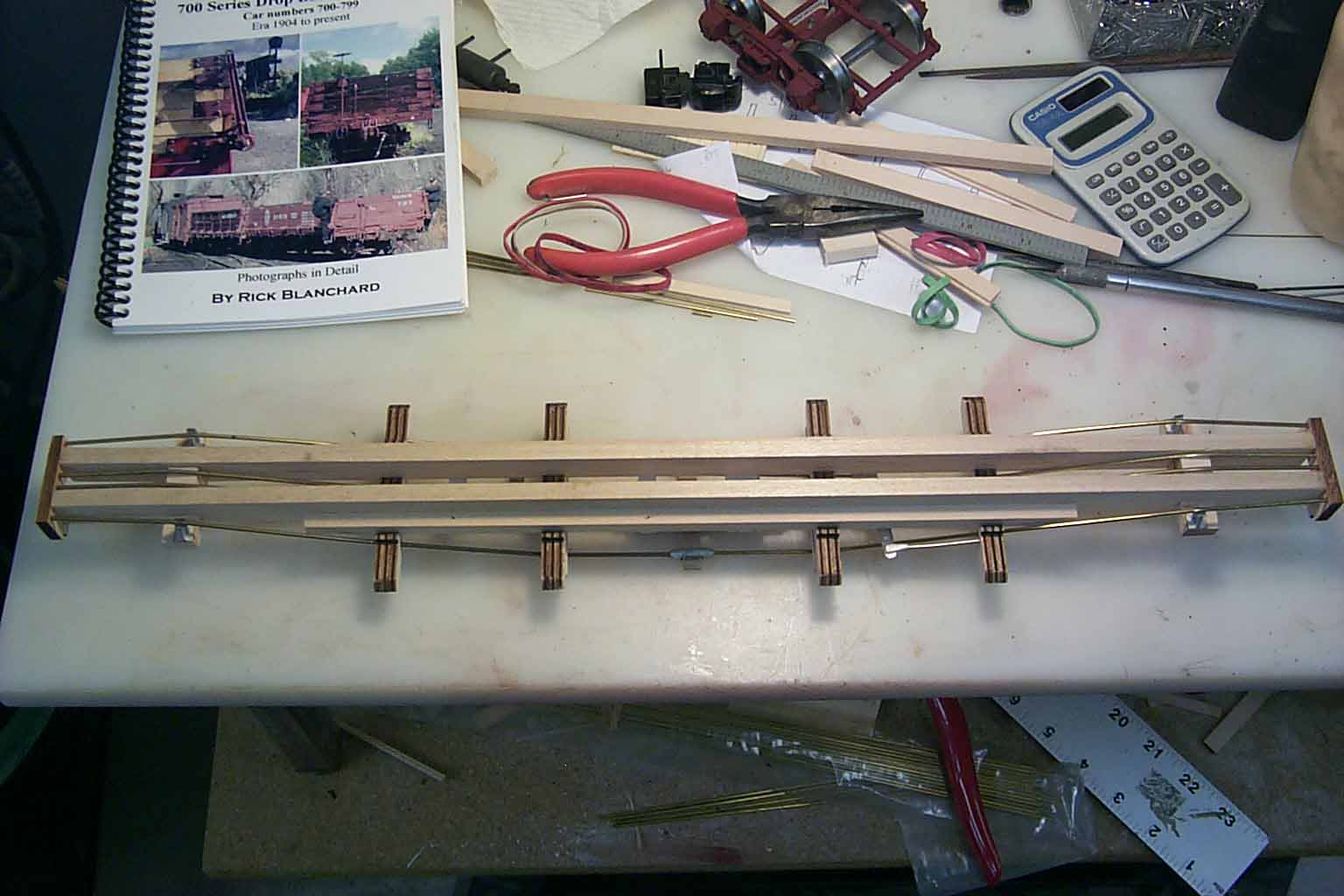
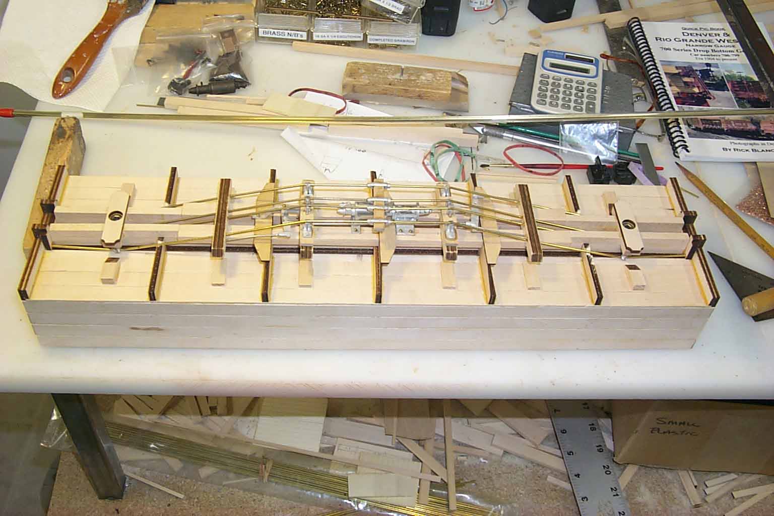
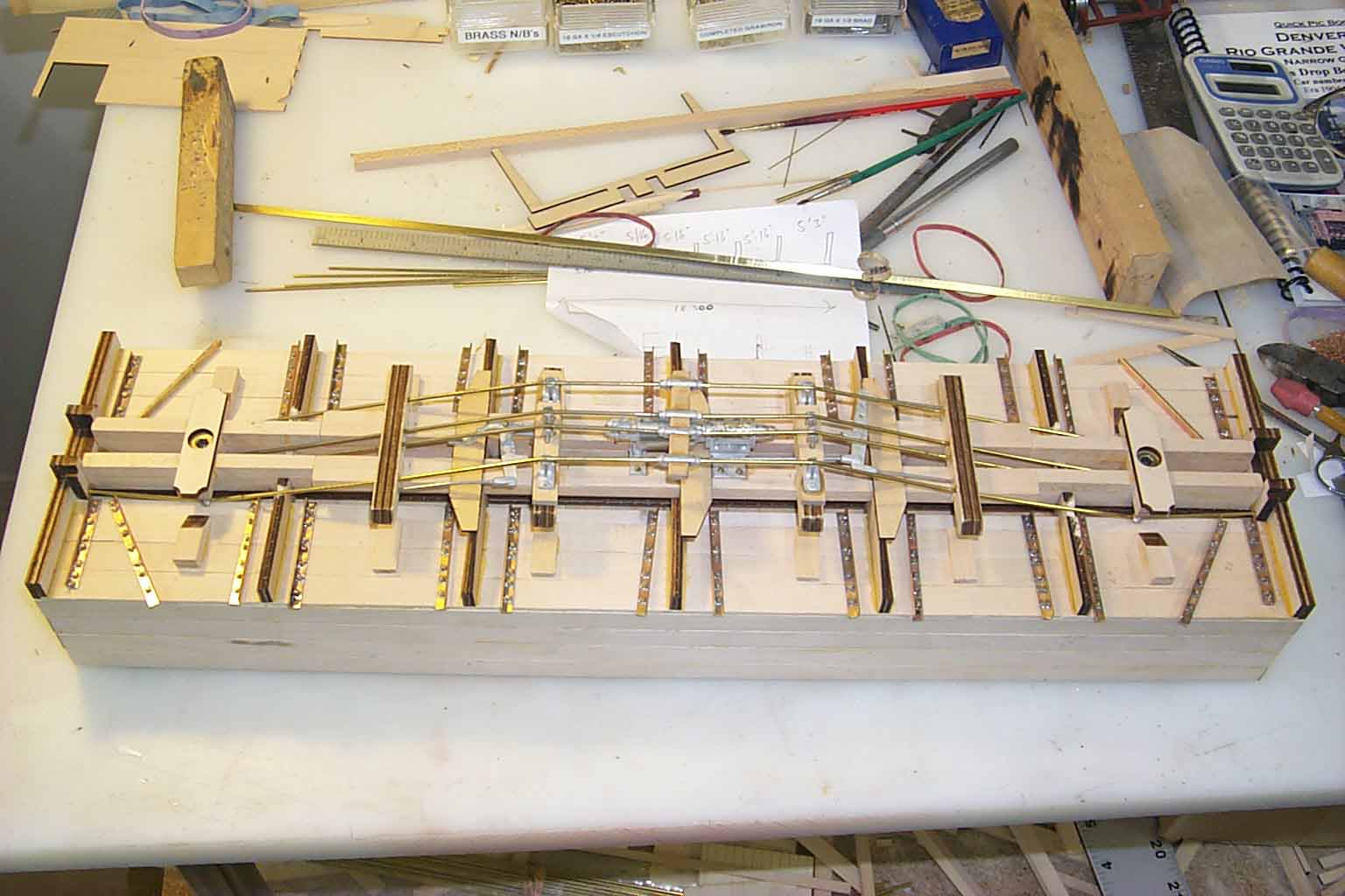
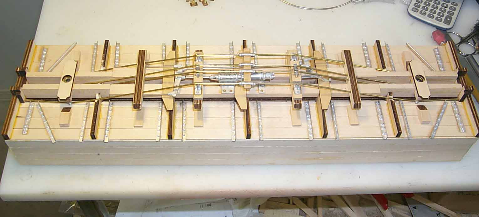
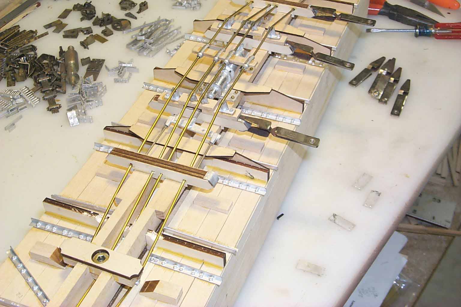
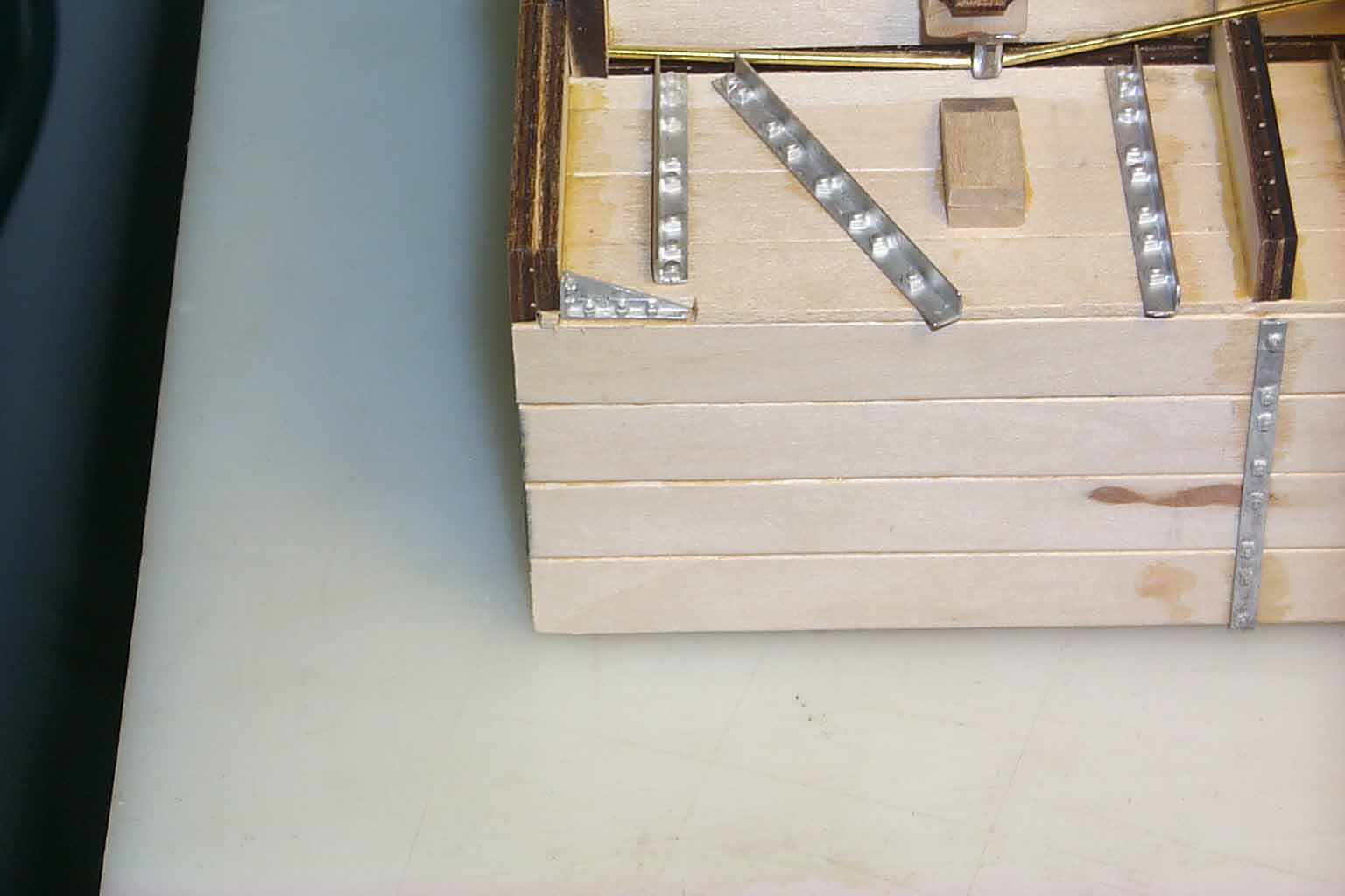
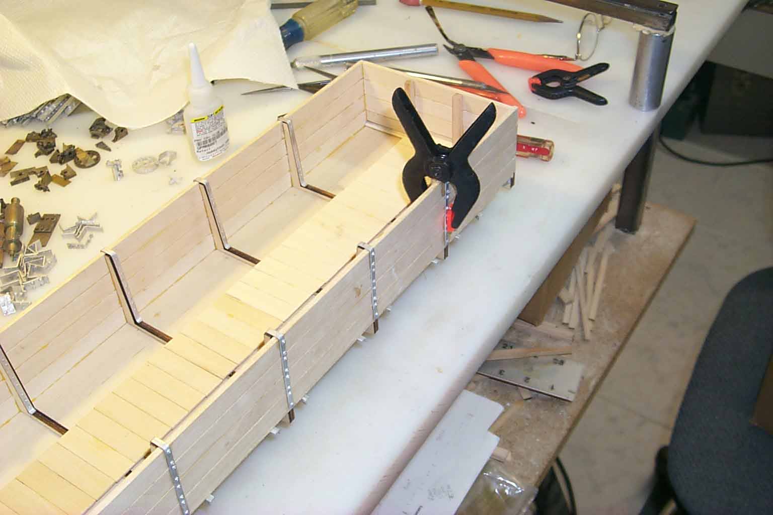
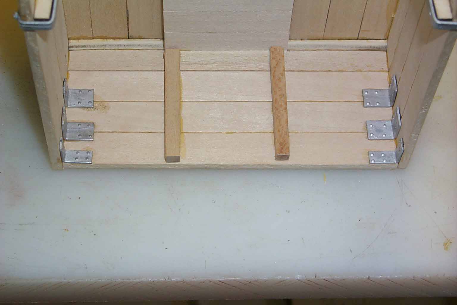
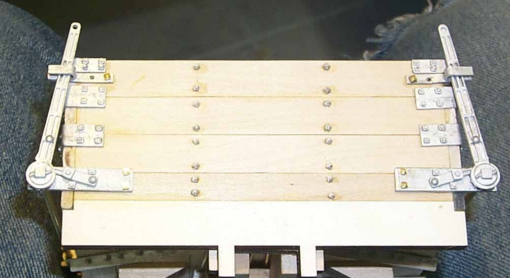
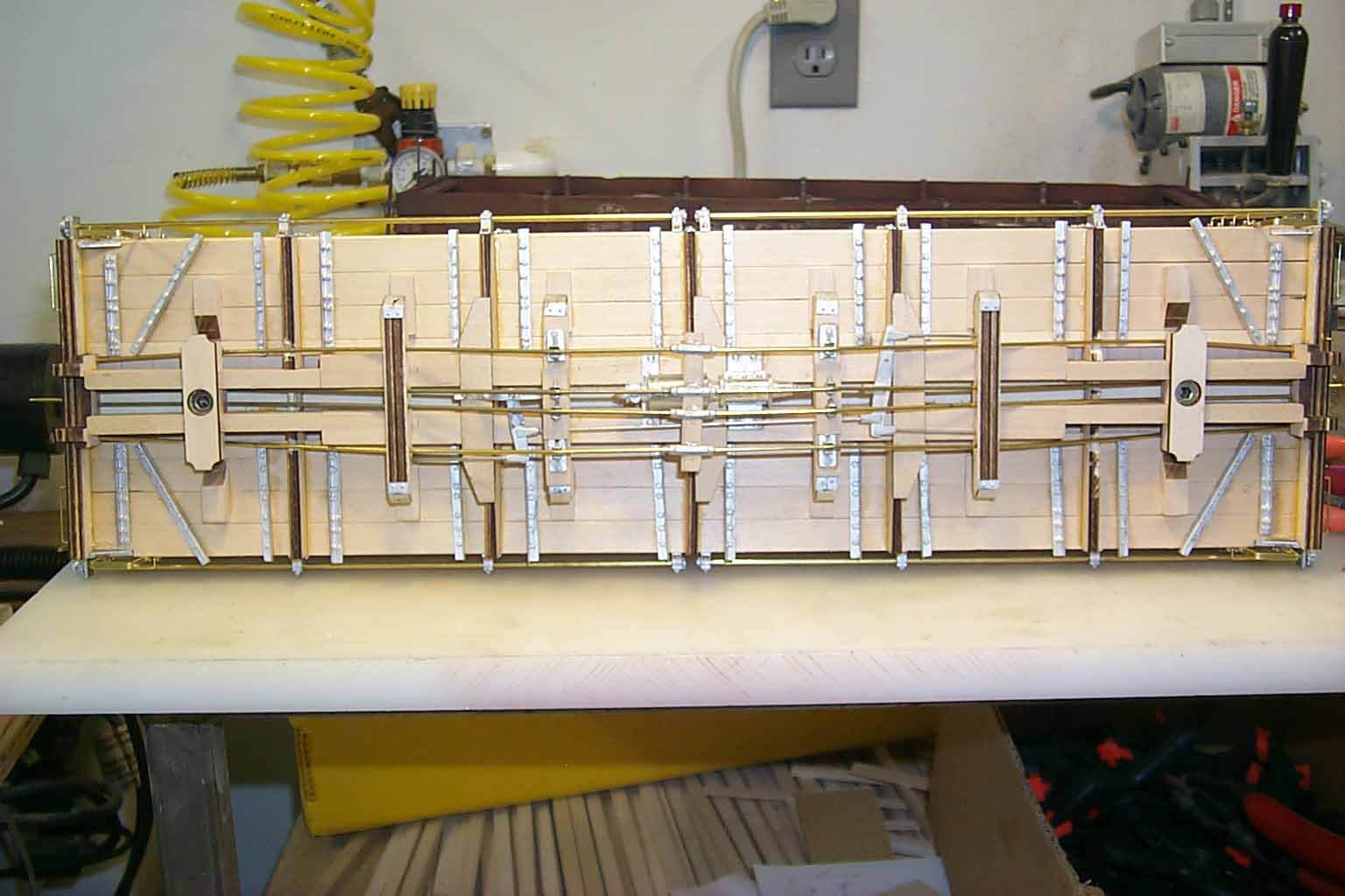
The drop bottom doesn't really have much of a frame in the since of a boxcar or other type of "house" car. But there are the center beams and drop door stop beams of which 2 double as needle beams. The placement of these beams is critical so that the truss rods will install without any "magic" bends. The pictures that follow are of a "mock up" that will become the kit.
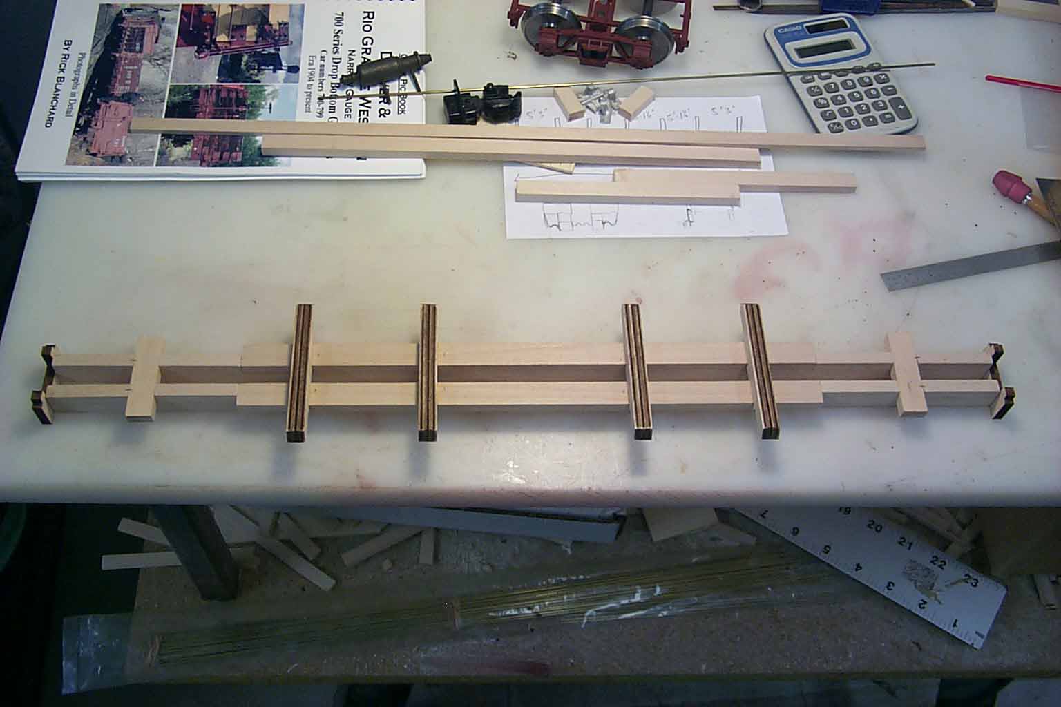
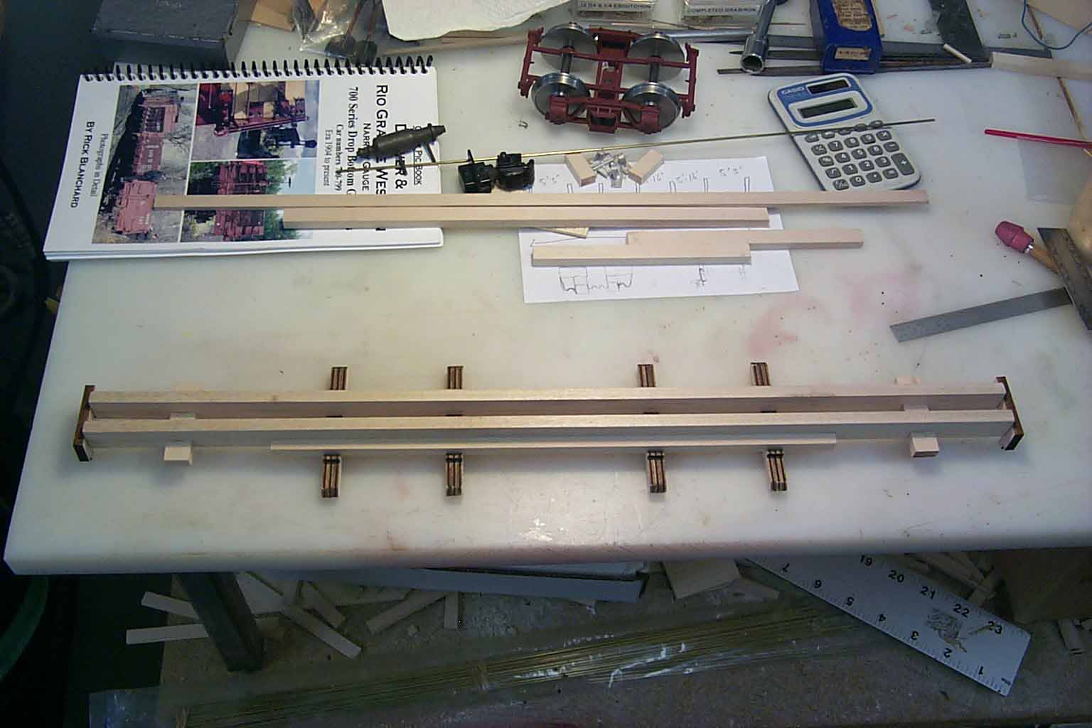
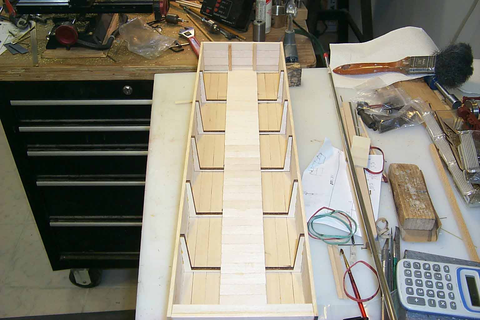
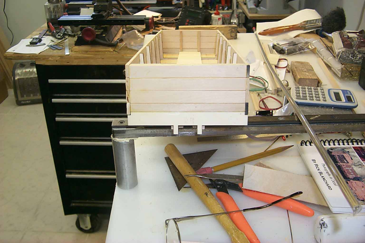
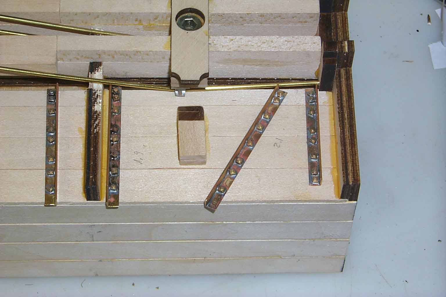
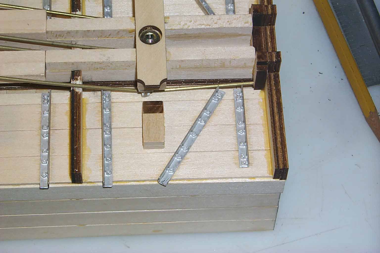
The 2 pictures are of the bottom and top of the frame that will be assembled in each kit. This will fulfil the following:
1. Place the body bolsters at the correct location.
2. Place the 4 drop door stop beams / needle beams at the correct locations.
3. Maintain proper spacing of the main center beams. These beams will be notched for sufficient rotation of the trucks to negotiate 8' to 10' diameter curves.
While this frame looks relatively simple (and it is), several hours were spent testing for proper size and placement. The kit is being designed to sit on Accucraft 3' 7" freight trucks. The use of any other truck will cause the car height and truck pivot to be unsatisfactory.
I still need to build the jig for mass producing this frame. I should have that by the next update.
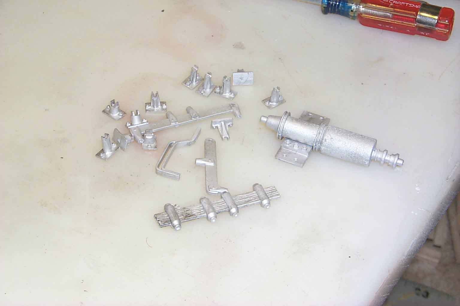
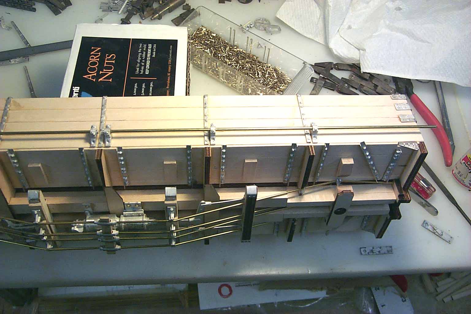
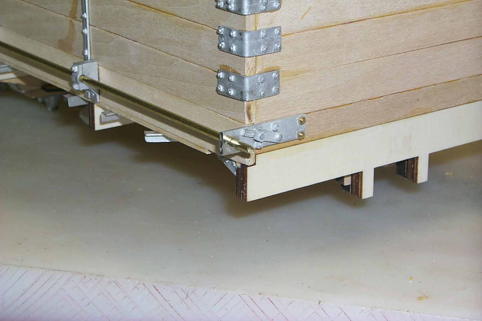
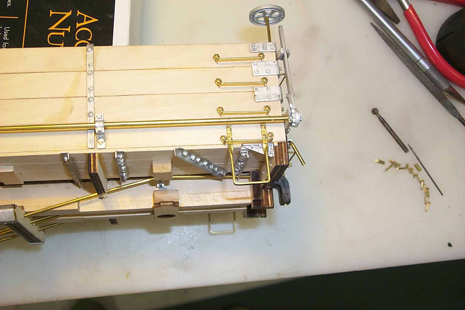
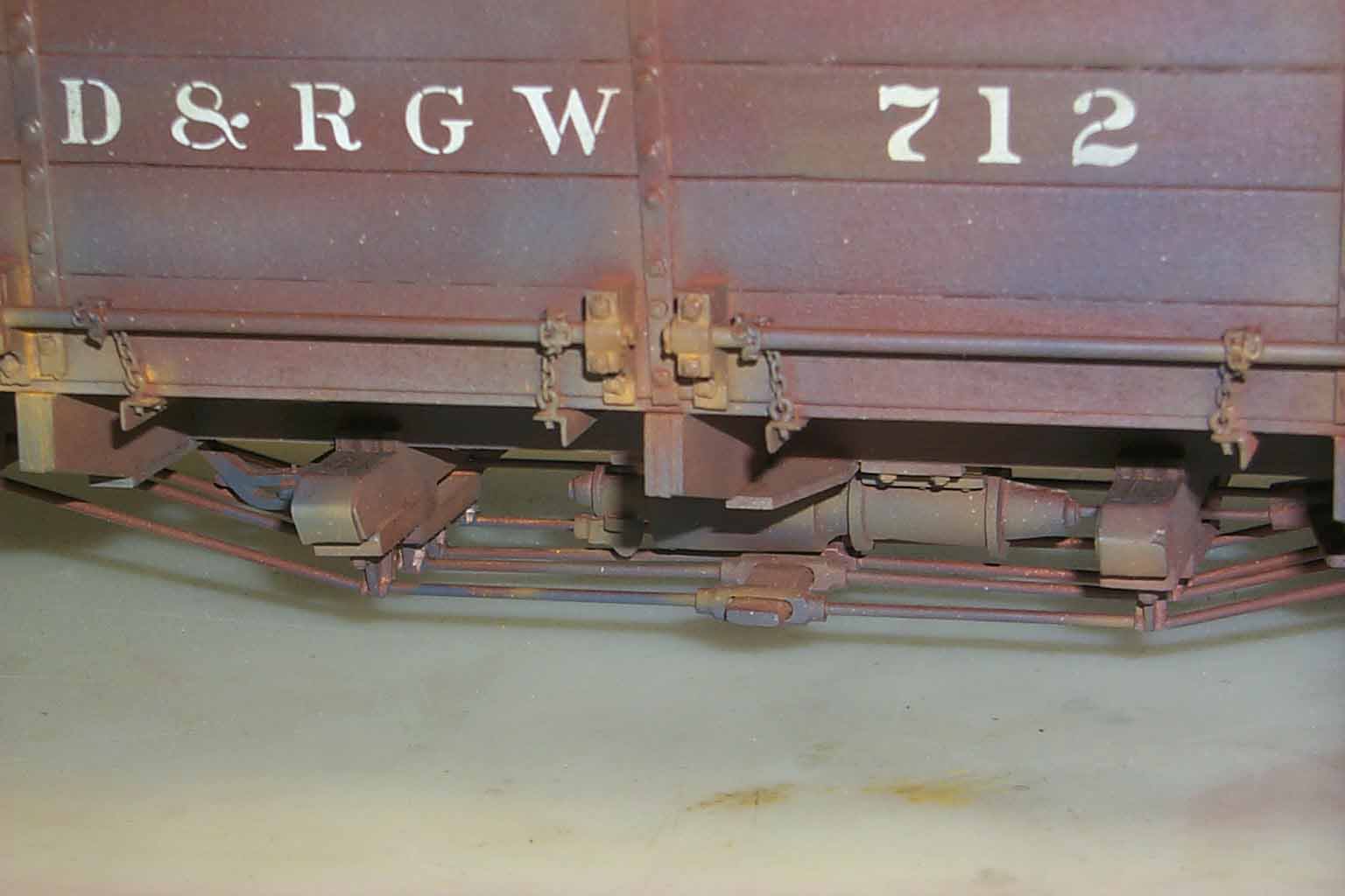
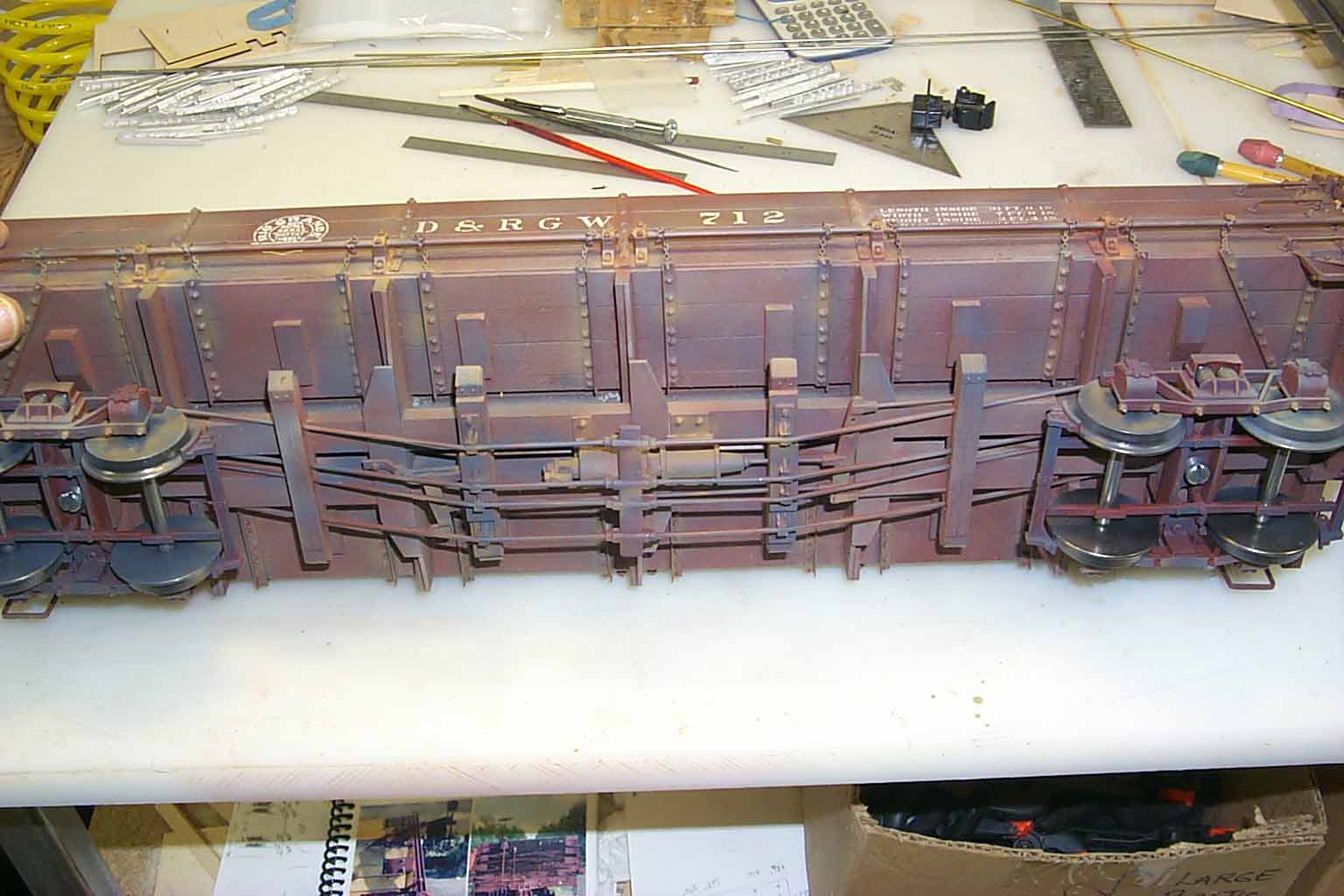
Assembly of the kit is going to jump from assembling wood parts to metal parts and back several times. The complexity of the truss rod placement dictates this so here's a look at brake and truss rod placements.
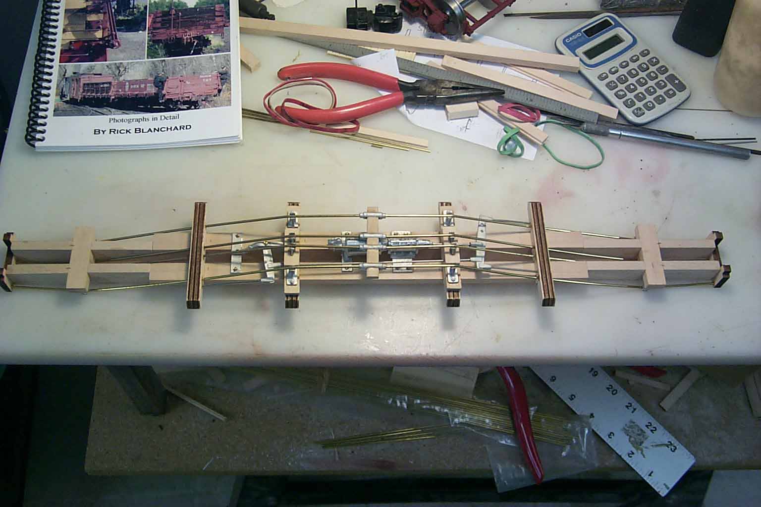
For the purpose of "cobbing" together the "first cut" of the kit, I used boxcar hardware for the brake gear, queen post and turnbuckles. I had to grind down all the queen post for them to fit. New masters of these parts will be made. Unlike my other kits, the truss rods will extend all the way to the end beams of the car.
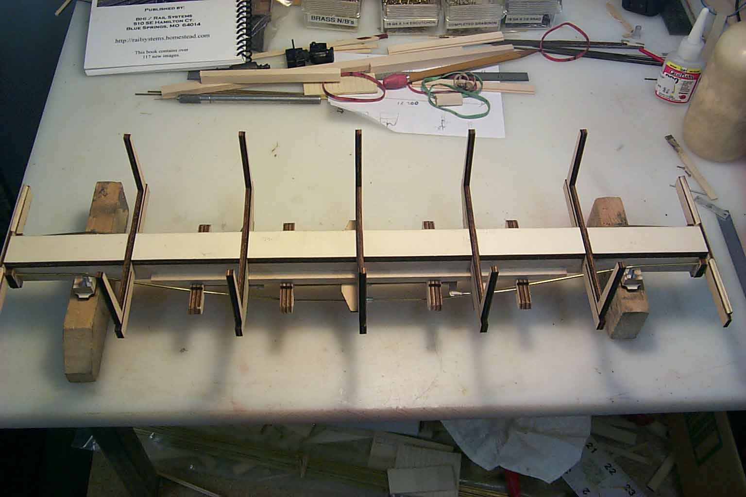
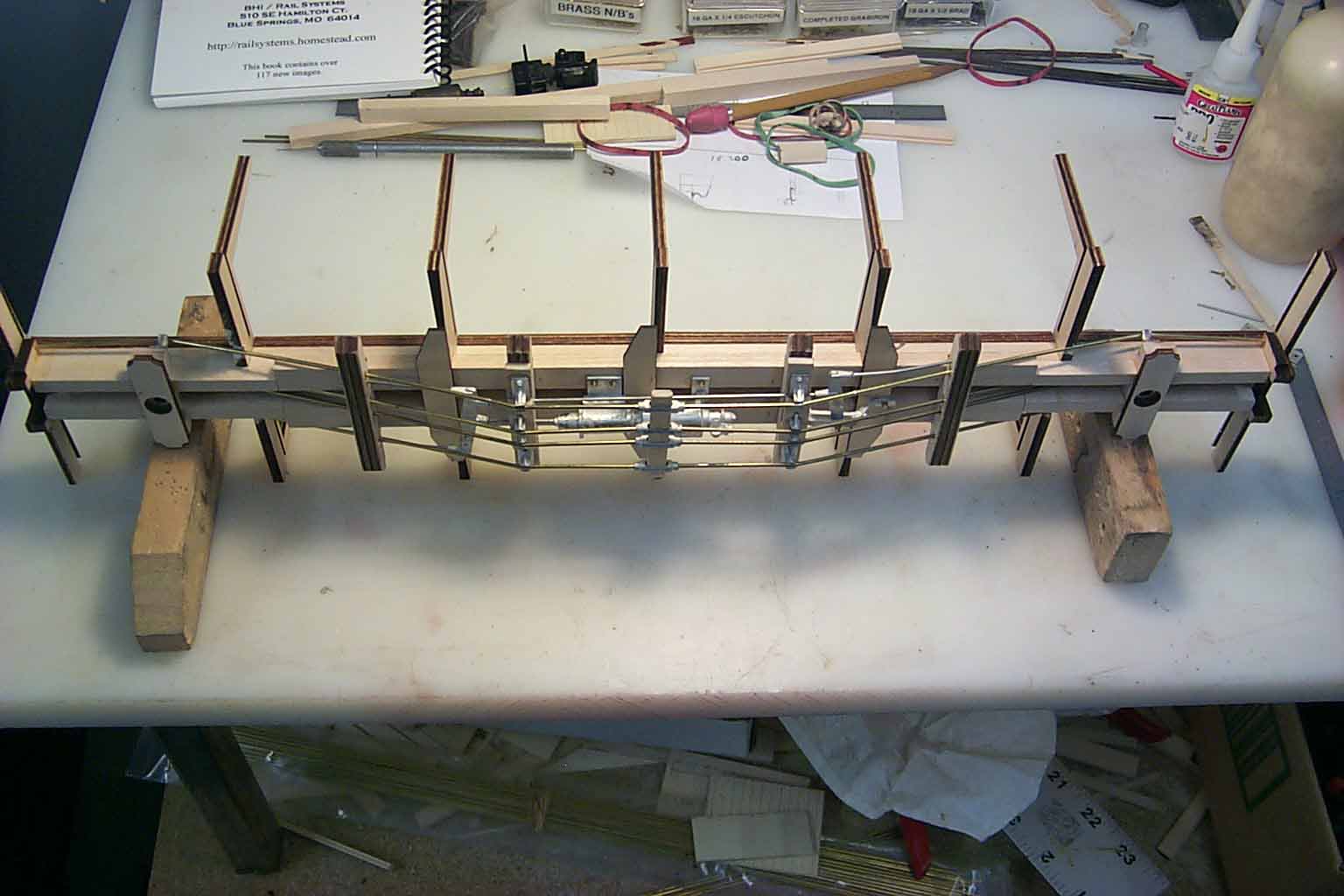
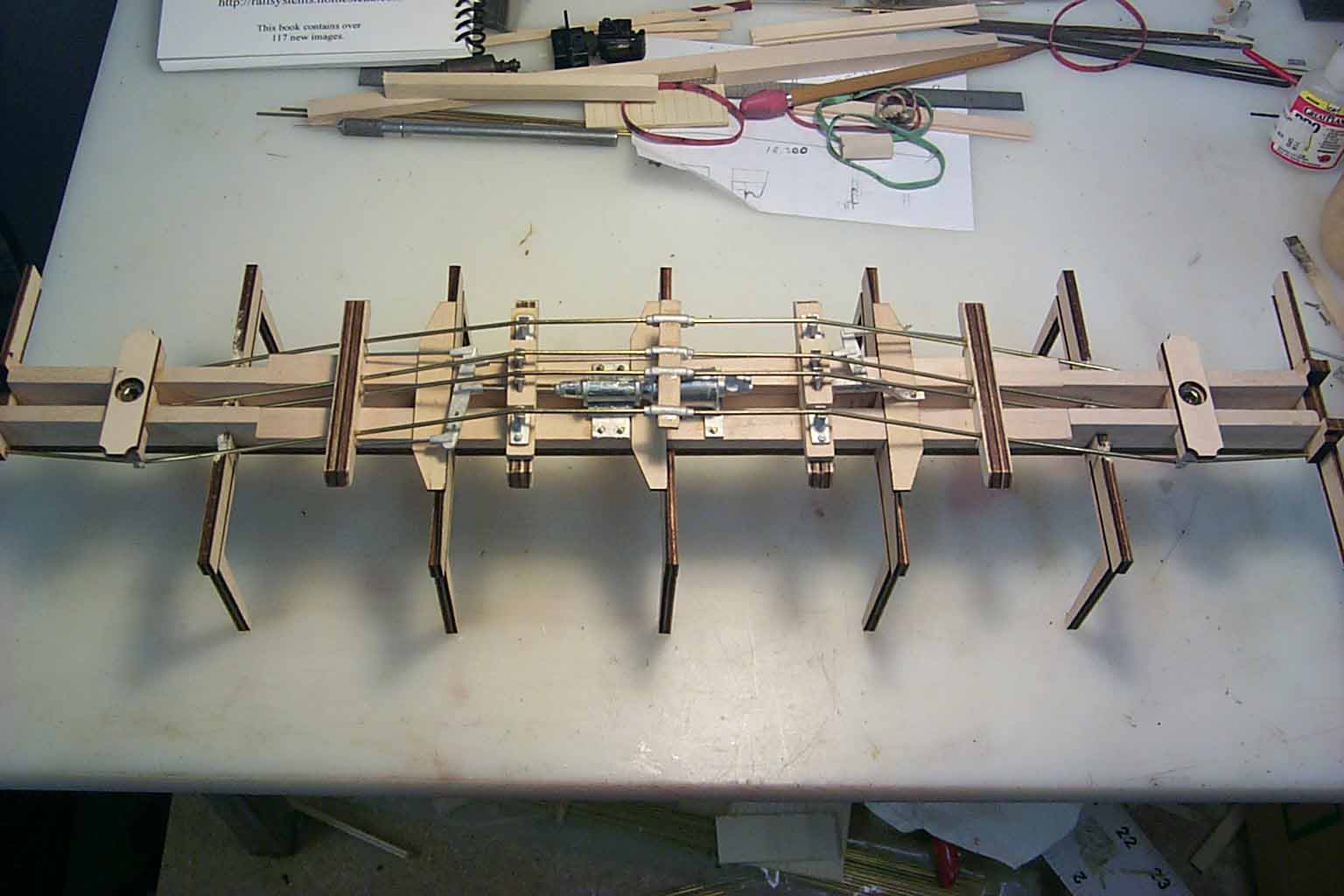
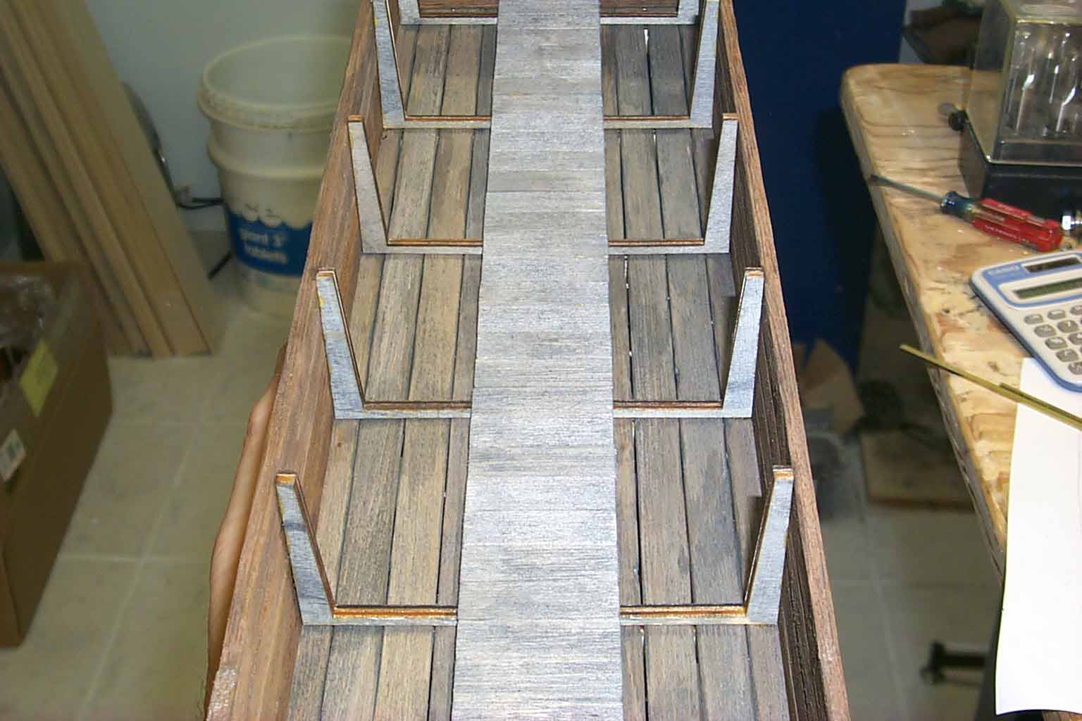
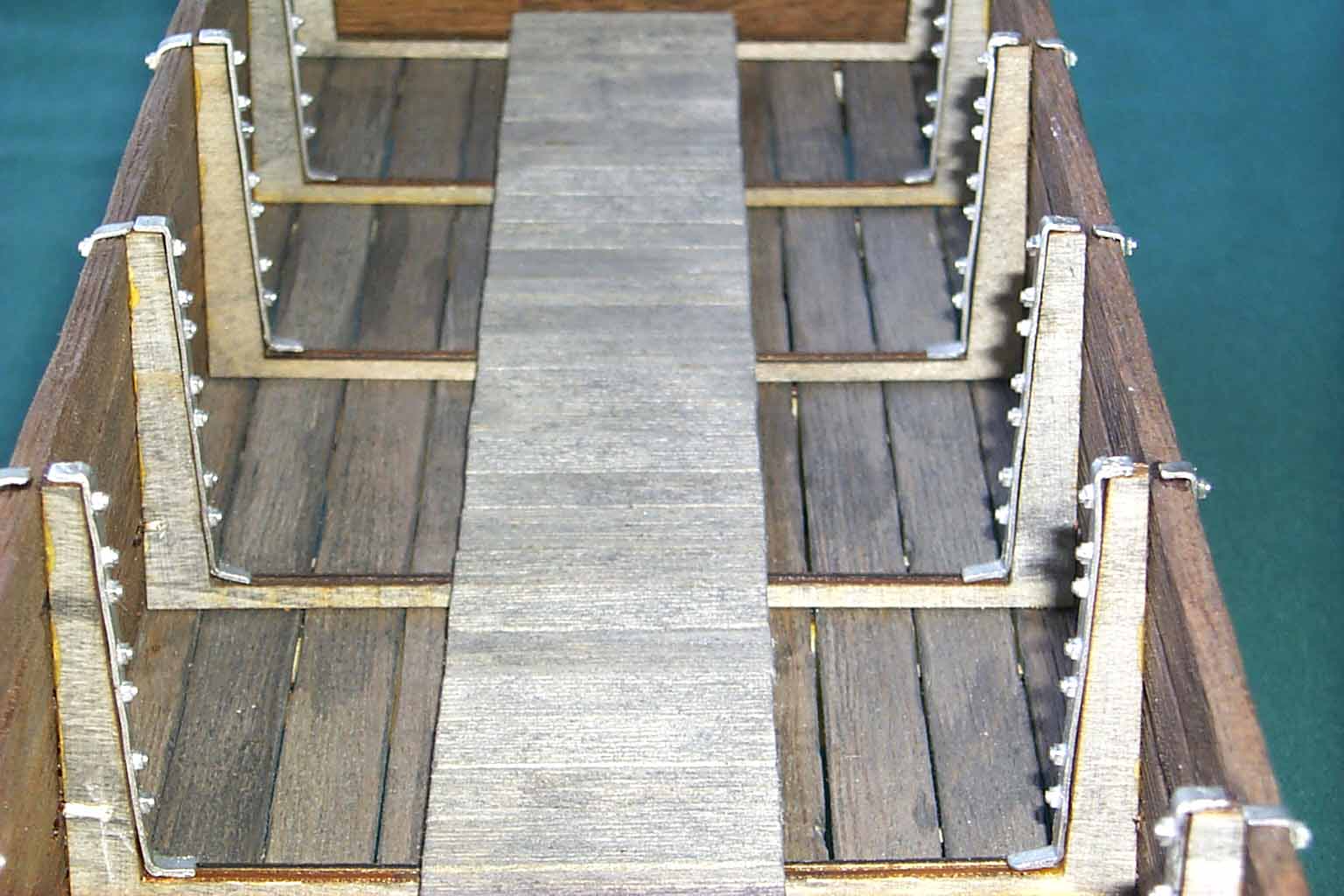
Pictures above is the frame with the "yokes" attached. On Don's kit, he used 7 yokes, 2 of which are located at the ends of the car. This is not correct but was a compromise he made to ease in the construction of the car. Don also notched the center beams for the placement of the yokes. On the PNG kit, I am using spacers glued to the tops of the center beams to correctly position the 5 yokes. The end beams are notched like the yokes to accept the floor boards. Like Don's kit, the doors will not open. I have also adjusted the height and width of the yokes to be per specifications of the prototype car.
Next update, we'll add the floor, walls and ends. We'll also start making masters for all the detail parts.
See you next time...................................
Phil
Update 3, 11-11-2007
Lets get the sides and ends cut and glued on.............
The next step is a long one. Cutting new brass masters for all the spin casting molds. First up, I made 29 angle braces for the bottoms of the drop doors.
Then I vulcanized a mold with all the masters and cast these parts in white metal.
The new door braces verses Don's laser cut styrene.
Next up was the underframe corner braces and the drop door, stop beam, end wrappers.
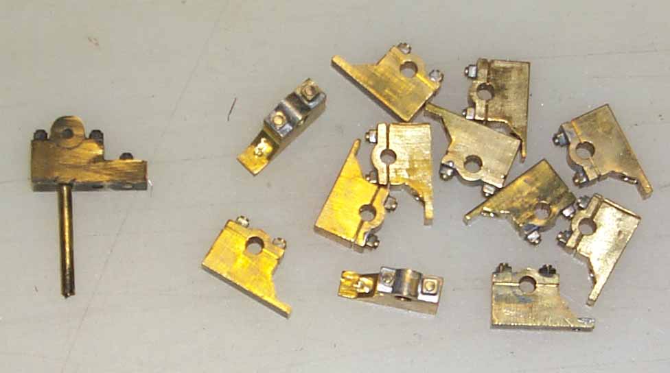
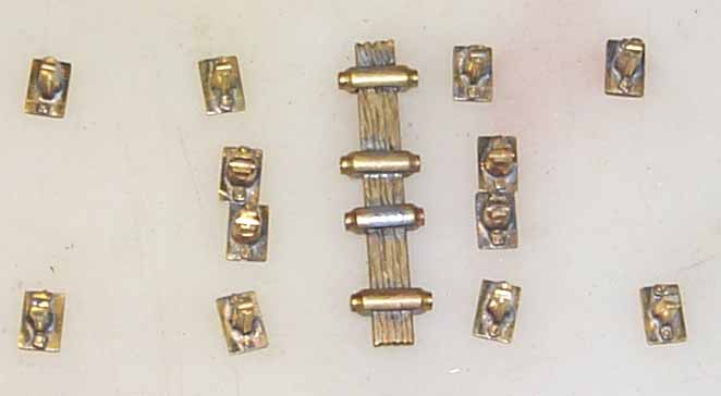
Then the pillow block chain rollers. Don's master is to the left.
Followed by the larger queen post. Small post yet to be cut. Don's Styrene queen post are at the bottom. I still need to add the NB's to the masters. One on each side of the post.
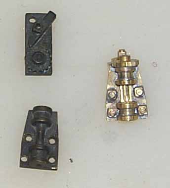
And finally, my version of the brake cylinder and bracket. This is a 2 part unit. The bottom of the cylinder is notched for the bracket.
And finally, my version of the brake cylinder and bracket. This is a 2 part unit. The bottom of the cylinder is notched for the bracket.
That's it for this update. I still have to finish the large queen post and make 4 small post. The turnbuckle assemble and brake levers will complete the underbody parts. Then I have to make the outer and inner corner braces, yoke straps, handle brackets and "B" end brake hardware. The list is getting smaller. Hopefully, I won't have as many interruptions in the next couple of weeks and can finish this project up.
See you next time..............................
Phil
Update 4, 11-27-2007
Lets get the rest of the brass masters finished.........................
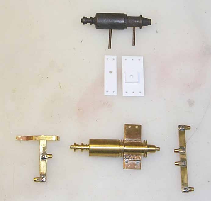
Here's my finished underbody brake gear and Don's brake cylinder and styrene mounting plates. A side note, Don's masters look almost black in these pictures. It's caused by two things. One is the sulfur in the raw rubber of the molds. When vulcanizing, the sulfur reacts with the brass and turns it a dark carmel color. The second issue is the humidity of southern Georgia where Don lived. If you look at the last picture in this update, you'll see the ratchet handles, lock pawls and drop door angle braces are all a nice carmel color where as the new masters are still shinny brass. I don't have the humidity problems of the east coast. If I was going to re-use any of Don's masters, I would have to clean the oxide off the parts. The rubber for the molds will stick to the oxidation otherwise and create an unsatisfactory cavity in the mold.
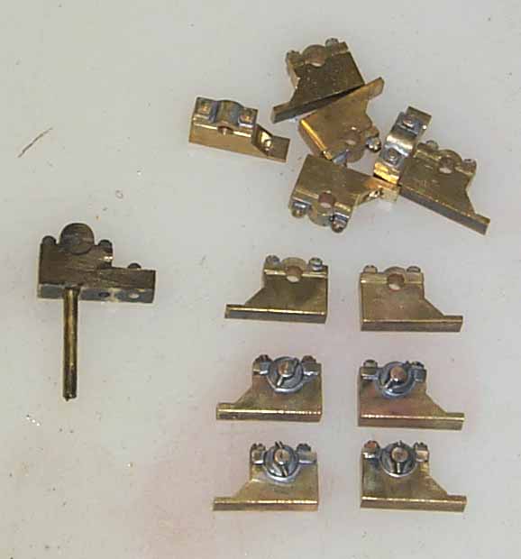
I added the chain roller ends, washers and bent bolt "cotter pins" to the pillow blocks. 2 left and 2 right for the center blocks on each side of the car. Don's master is on the left.
Upper brake staff support & lock pawl combination. Don's masters are to the left in the first picture.
The upper right is the top board, inside and outside corner braces. The lower left is the outside lower board corner braces. The lower right are the lower board inside braces. Dons master is in the upper left. Don only supplied 1 corner brace for each corner. The PNG kit will have 3 per corner, inside and out.
The finished tall and short queen post. Trying something different and making the turnbuckles and board one casting. I added wood grain to the "board" with a Dremel tool.
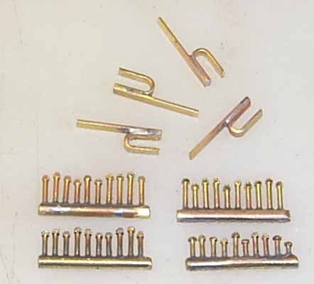
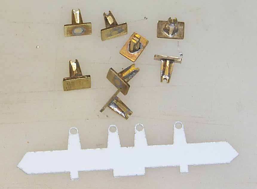
4 handle storage brackets and 40 ea. 1/16" sized NB's. These are used to bolt the end boards to the vertical end braces. The sides bolts used straps that went up the sides, wrapped over the top and down the inside of the brace. The end bolts didn't use these straps and were just bolted through the boards. These bolts are smaller than my PNG-NB's. These are cut from 1/16" square stock and the PNG NB's are cut from 5/64" square stock.
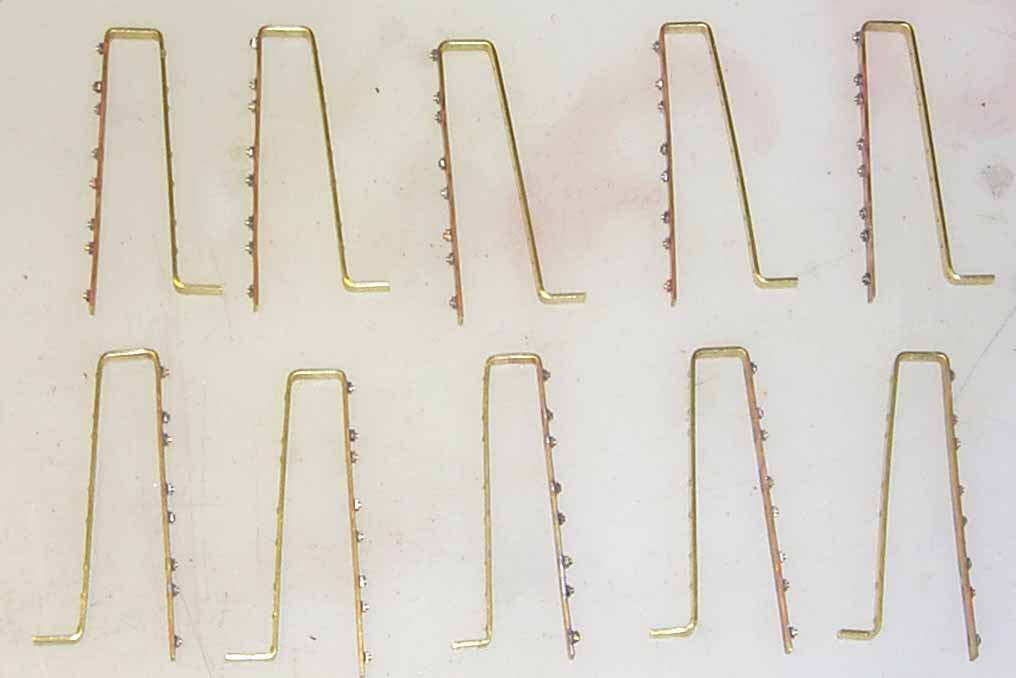
10 side strap / bolt patterns. The inside of the strap has a dimple to represent the rounded head of a carriage bolt.
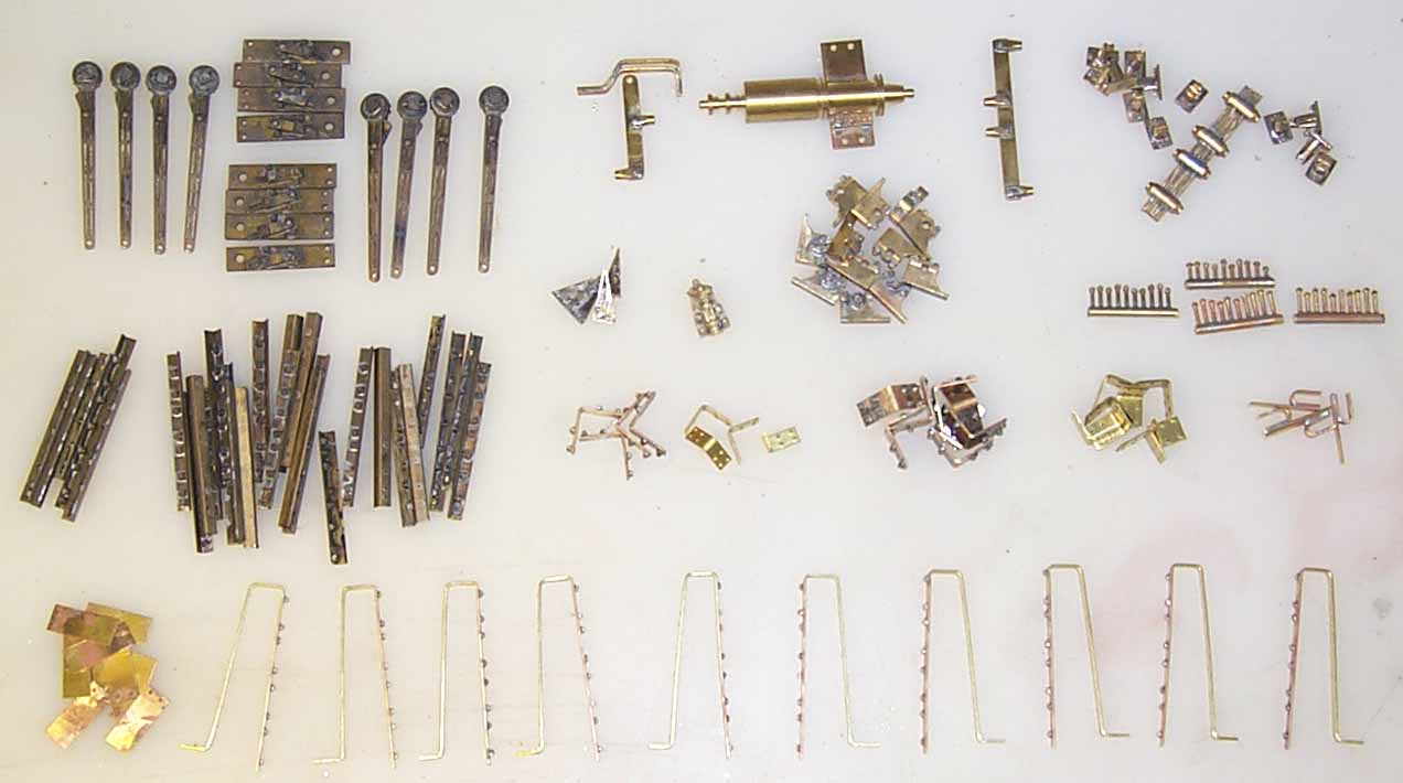
Finished!!!
May not look like much but represents close to 10 weeks of "on again, off again" work in the shop. Just for the record, building trains is not my full time job.
On the next update, I'll take you through the mold making process and turn these masters into white metal castings. Then we'll add them to the first cut car. We'll also make the frame jig so I can mass produce a nice square frame for the kit to build on. In the mean time, I'll order the necessary lumber so we can build the second cut car. All lumber and castings on this car will be production run parts. This insures everything in the bag will fit on the car. As the second cut car gets built, I'll take pictures of each step for the instructions.
Still, a bit more time to go before a price tag gets affixed to the kit but there is light at the end of the tunnel!!!
See you next time.....................................
Phil
Update 5, 1-4-2008
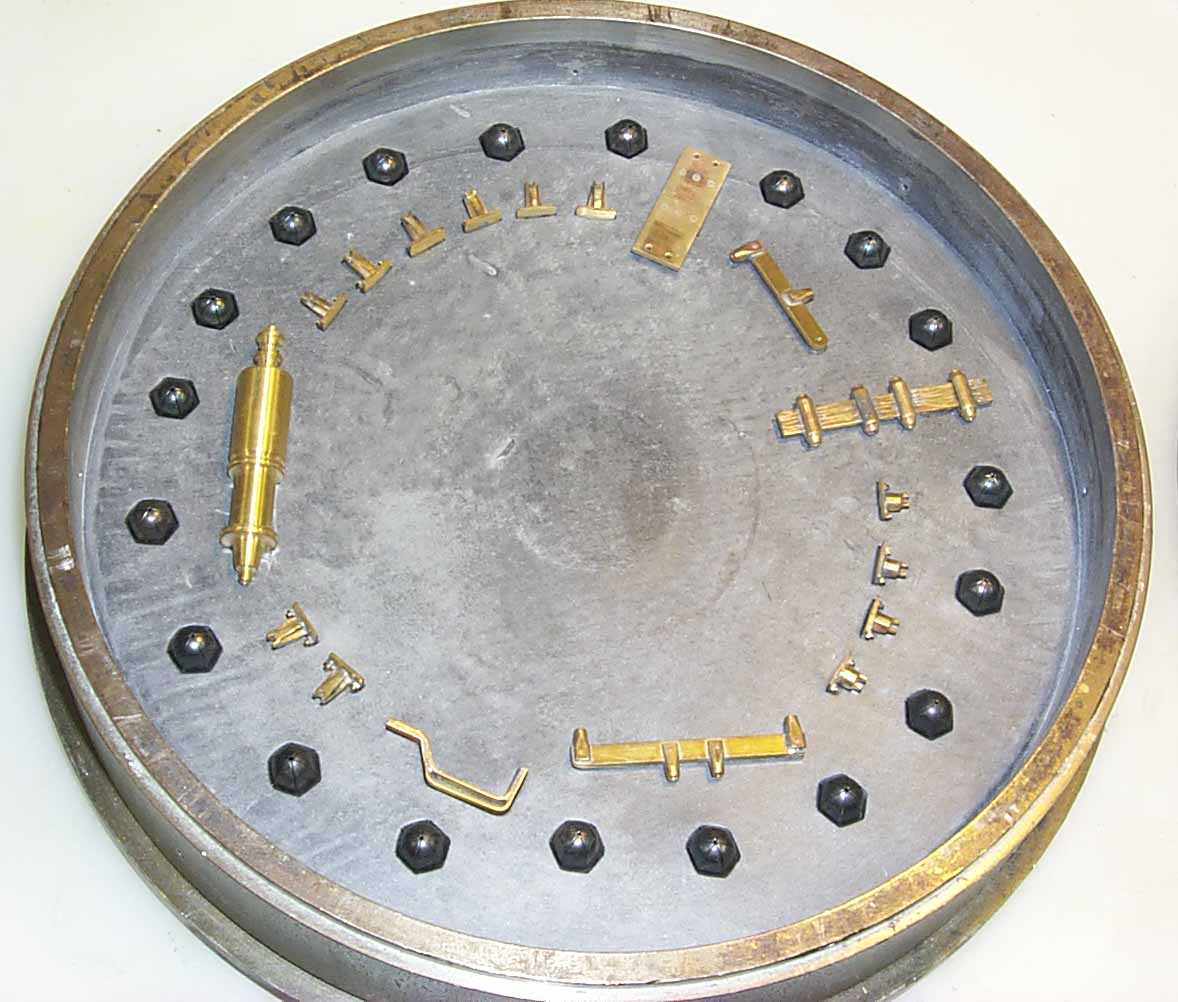
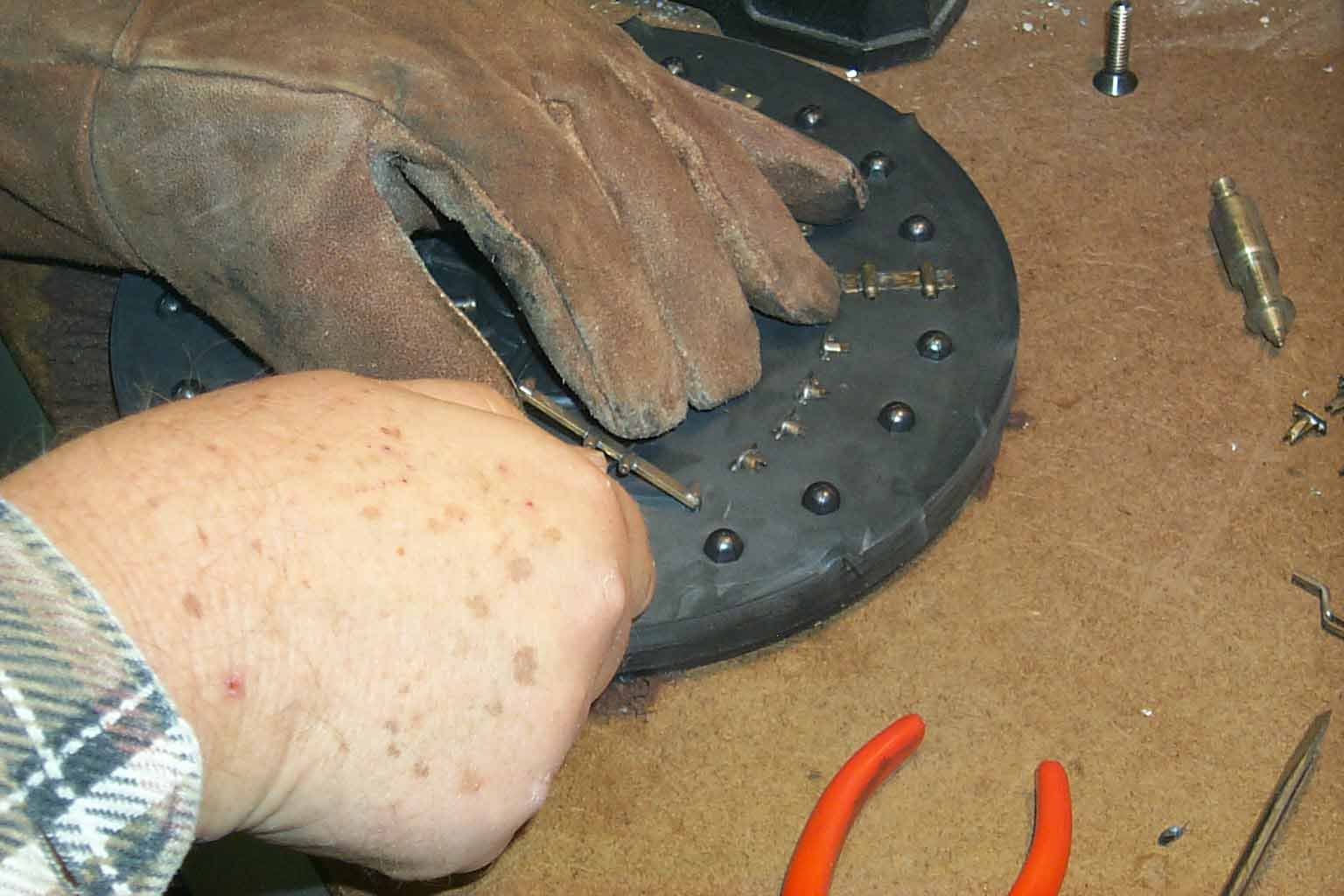
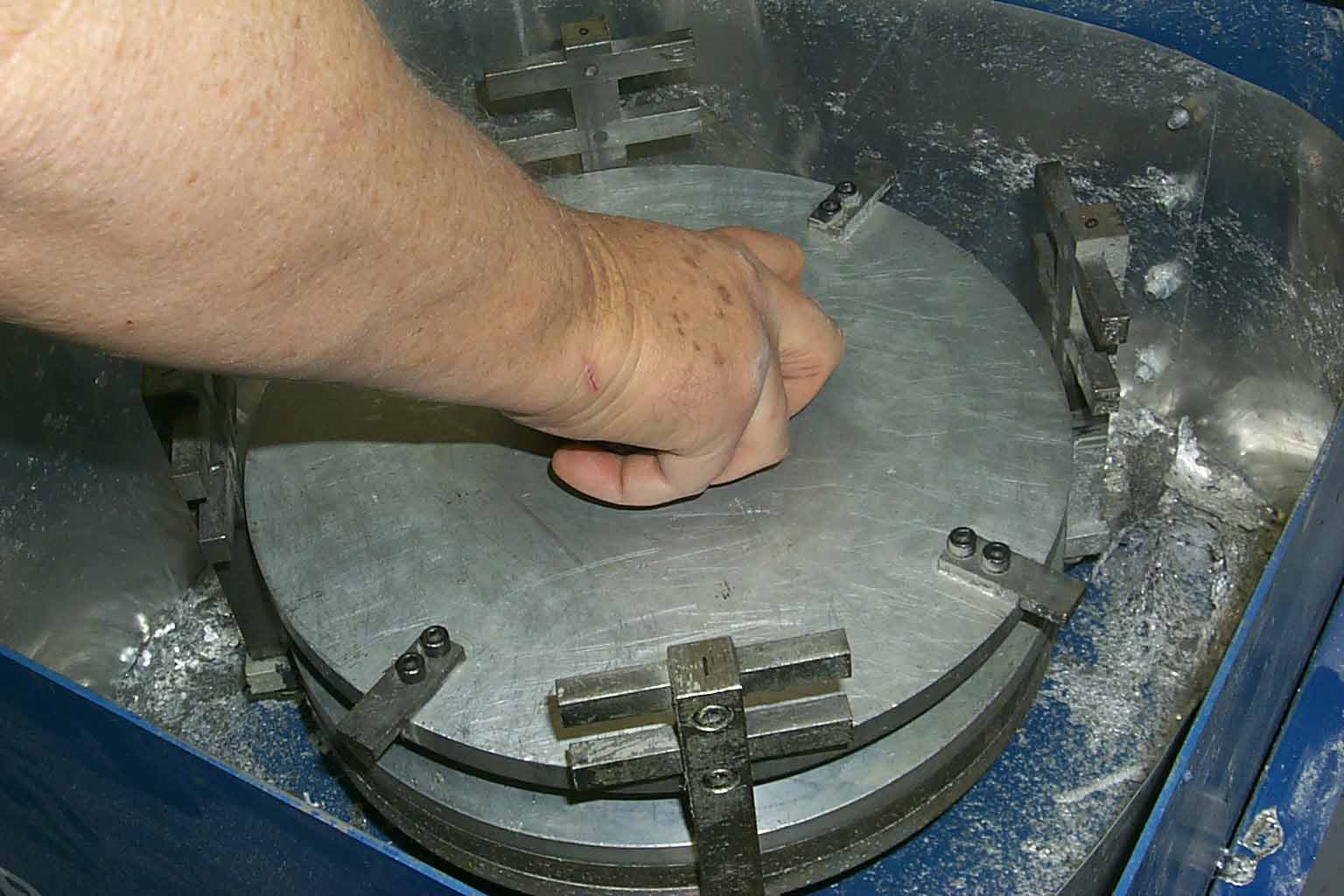
With all the masters finished, it's time to make some molds for spin casting the parts in white metal. I have 64 new pictures for this update and a ton of information for you to digest. The pictures will be thumbnails that you can click on to blow up. Hit your back button to return to this page. Each picture is numbered with a legend below each row.
![]()
![]()
1 2 3 4 5 6 7 8
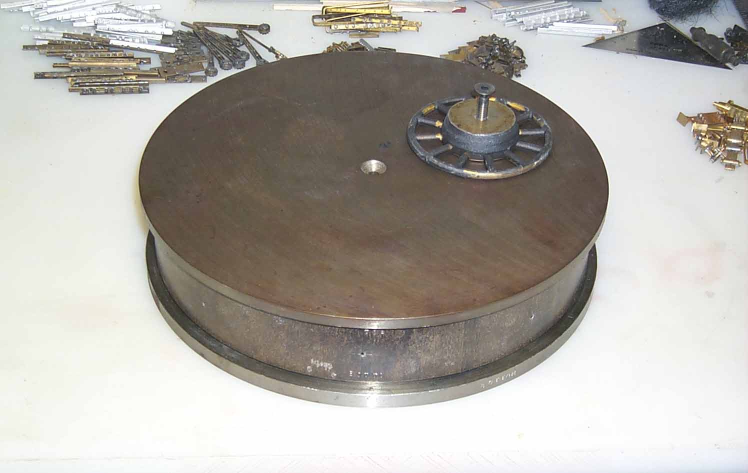
1. Steel vulcanizing ring and my custom gating device.
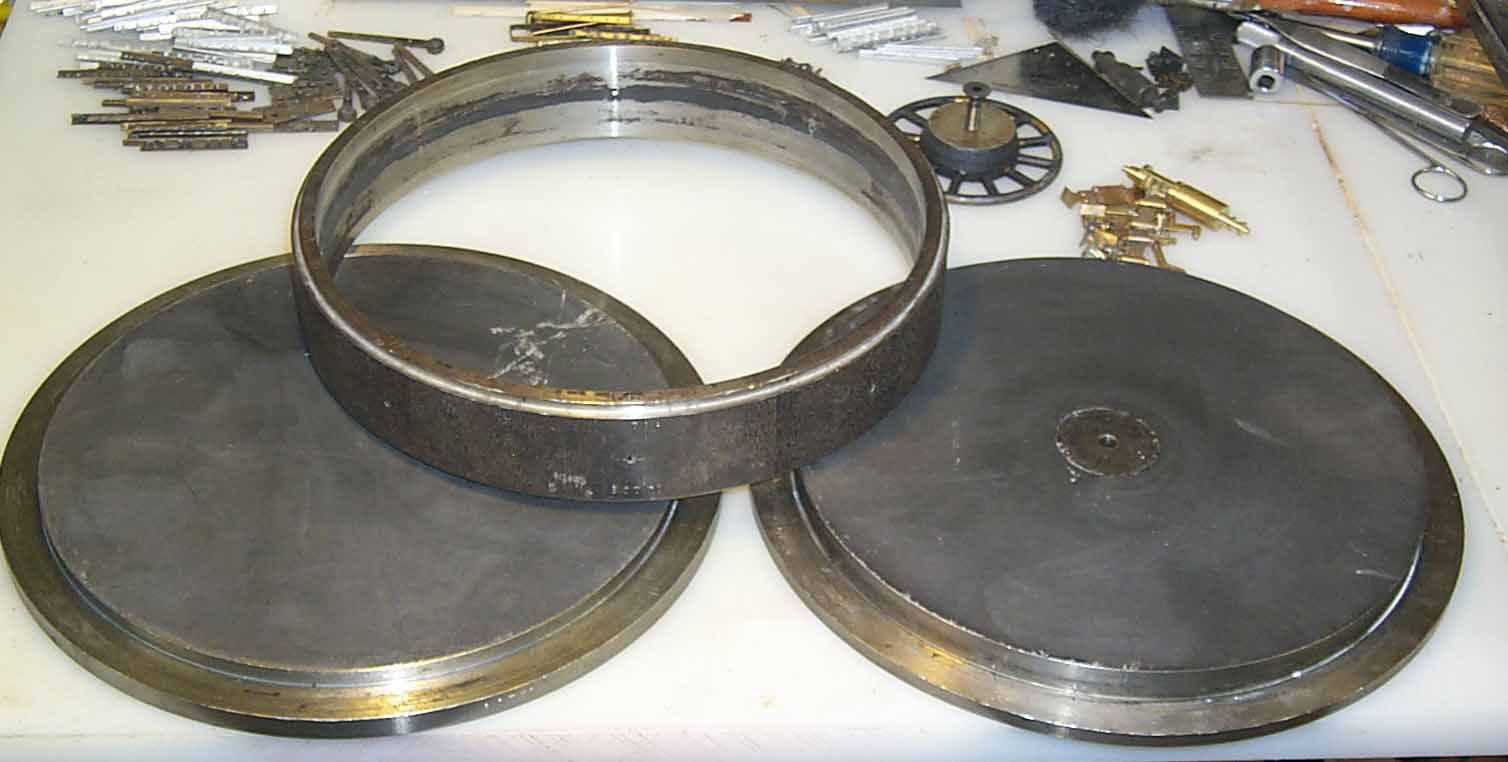
2. Bottom, middle and top of the ring.
3. My gating device attached to the top. This is just a reference picture to show you how and where the device fits.
4. The raw rubber. Bottom and top. Notice the top has a hole stamped in it.
5. The top piece with the hole popped out.
6. The bottom in the ring and the top and gating device attached to the top plate.
7. Brass masters laid out in the mold.
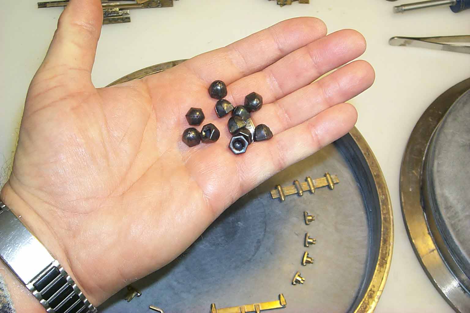
8. Acorn nuts. These are use as indexing for the top and bottom rubber sheets. They keep the two halves from shifting during the casting phase.
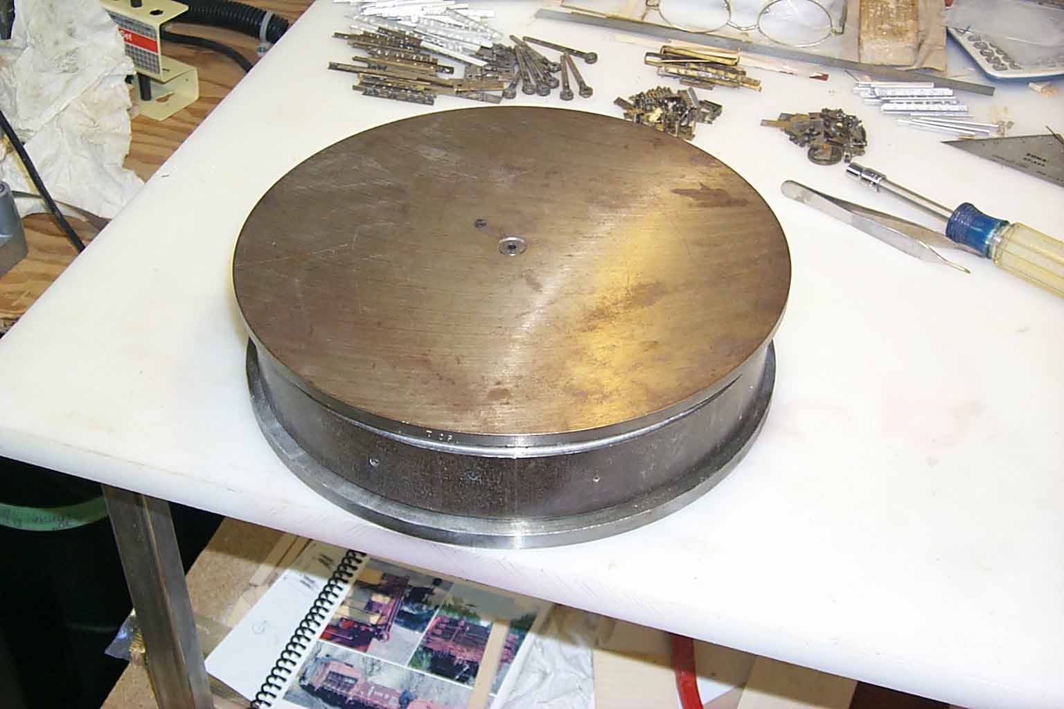
9 10 11 12 13 14 15 16
9. Brass masters and acorn nuts pressed into the rubber.
10. Lid on and ready to go in the vulcanizer.
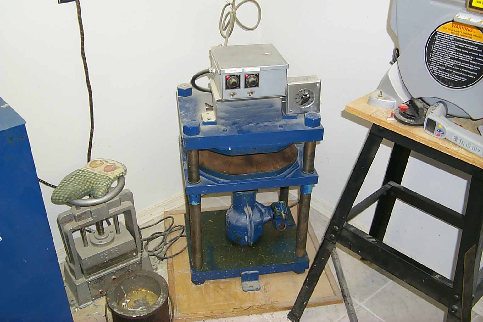
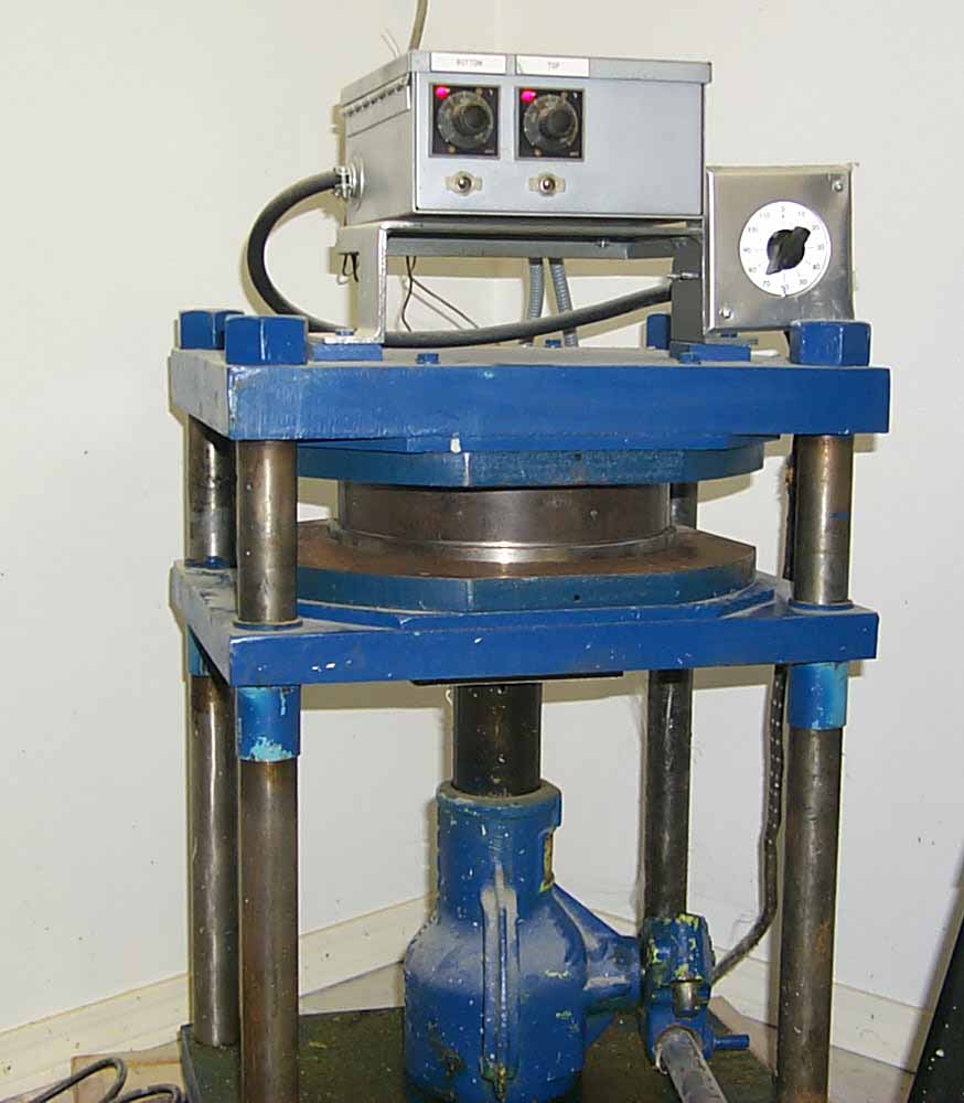
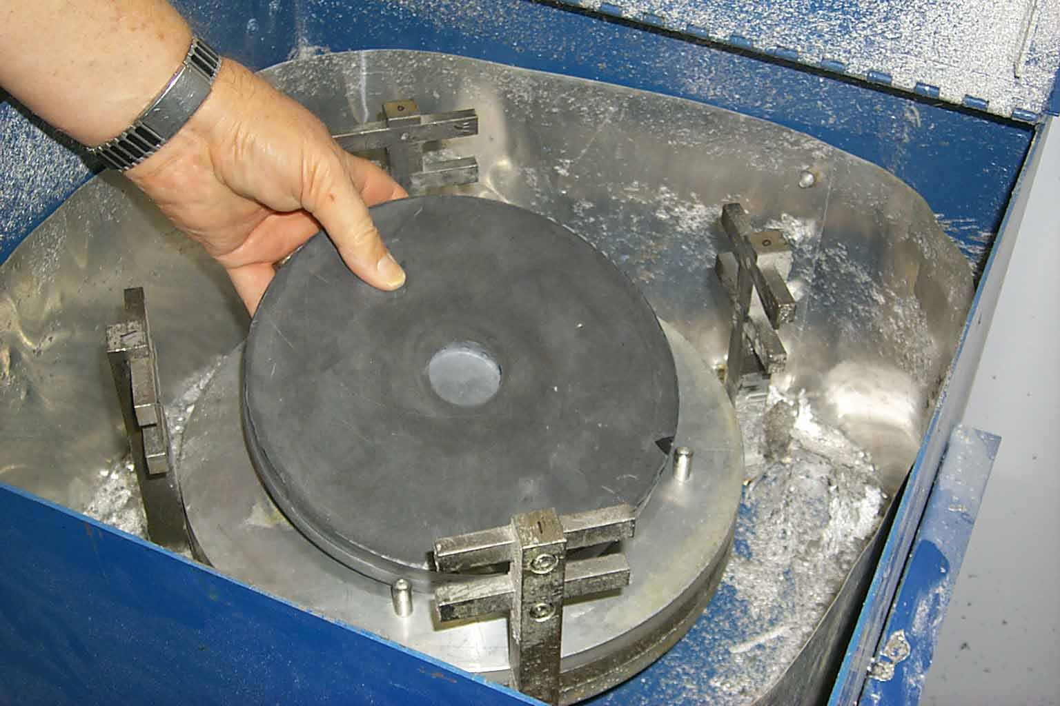
11. Romanoff vulcanizer.
12. Vulcanizing ring inserted and the hydraulic jack pumped up. Heaters are also on.
13. Something I do that others probably don't. I have 8 #60 holes drilled around the ring to vent the melted rubber. This acts as a pressure gauge so I know how much pressure to add or release from the mold. Too much pressure will cause rubber to blow out the top or bottom. Too little will not cause the rubber to surround the master properly and a failed mold.
14. Picking off the expelled rubber "shoe strings".
15. Hot, hot, hot. As is 300 degrees hot.
16. Removing the screw that holds the gating device centered in the mold.
17 18 19 20 21 22 23 24
17. Prying off the top.
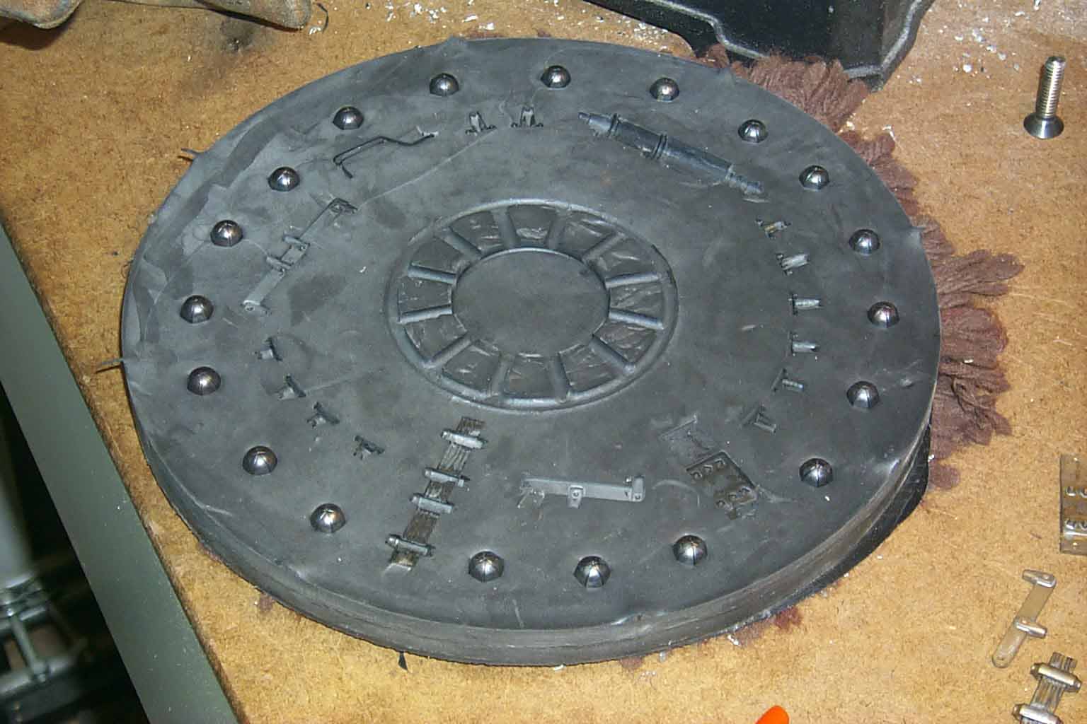
18. The "cake" is exposed.
19. Prying off the center ring.
20. Prying the rubber from the bottom plate.
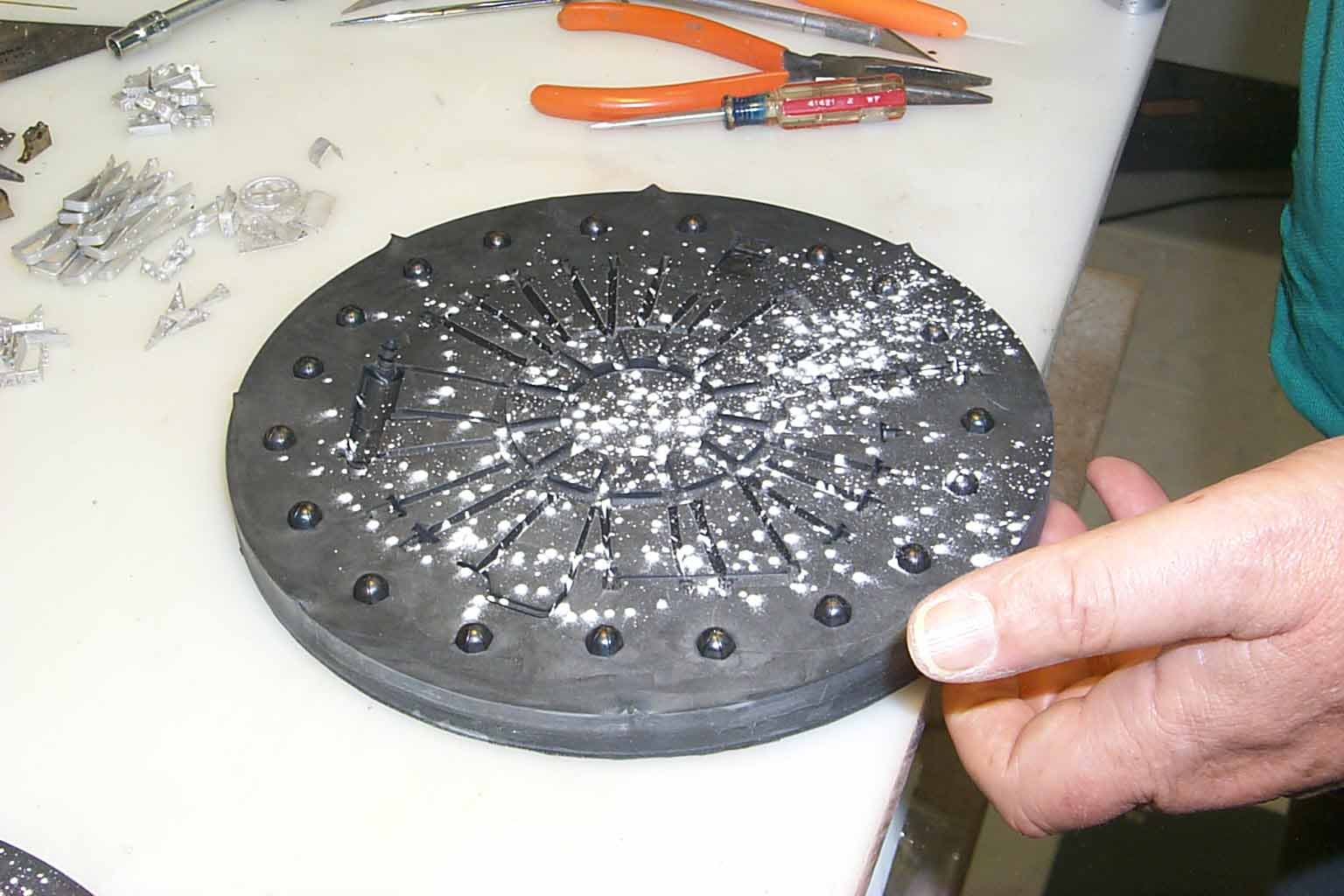
21. Separating the rubber halves. Talcum powder keeps the rubber halves from sticking together.
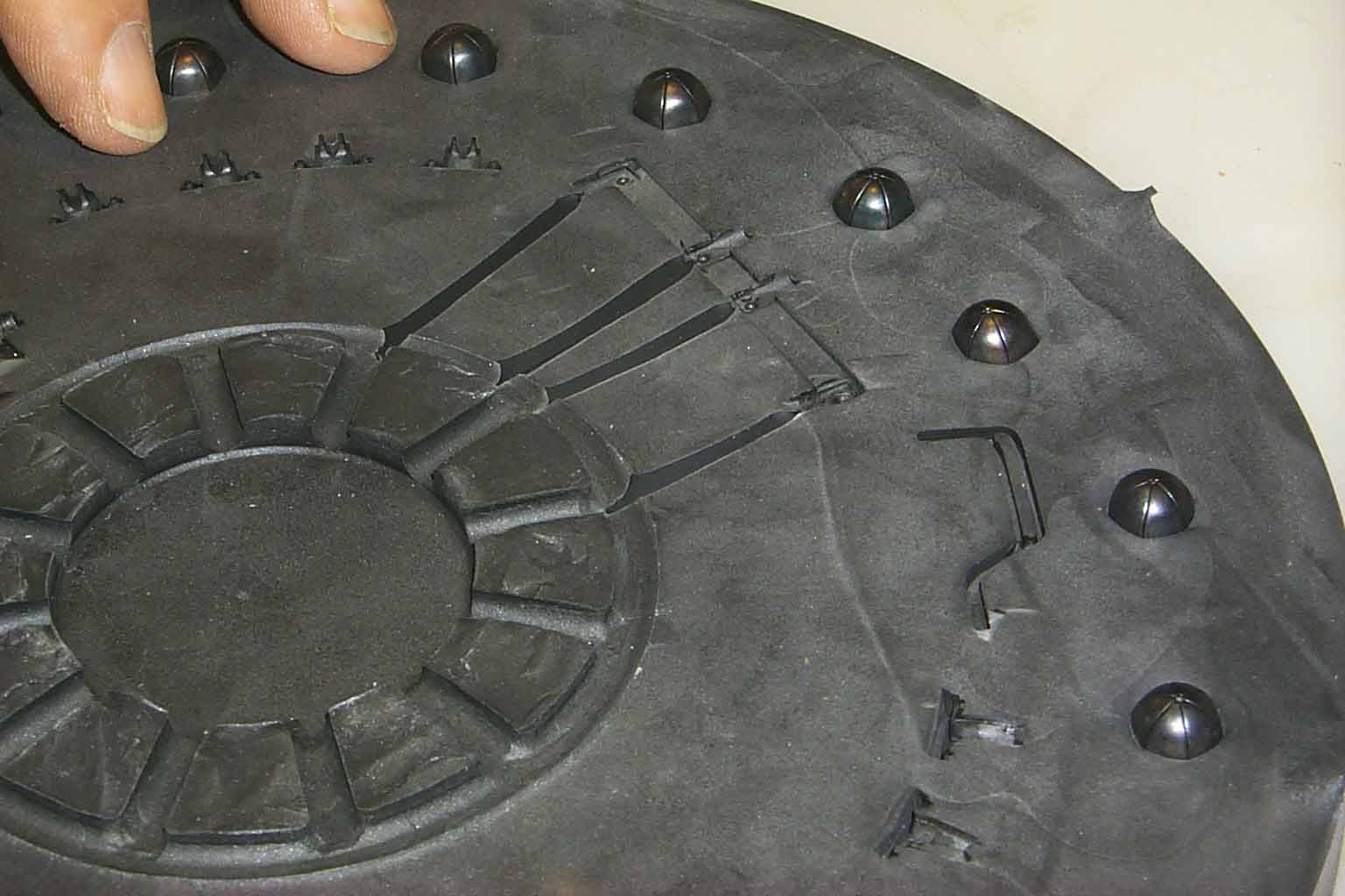
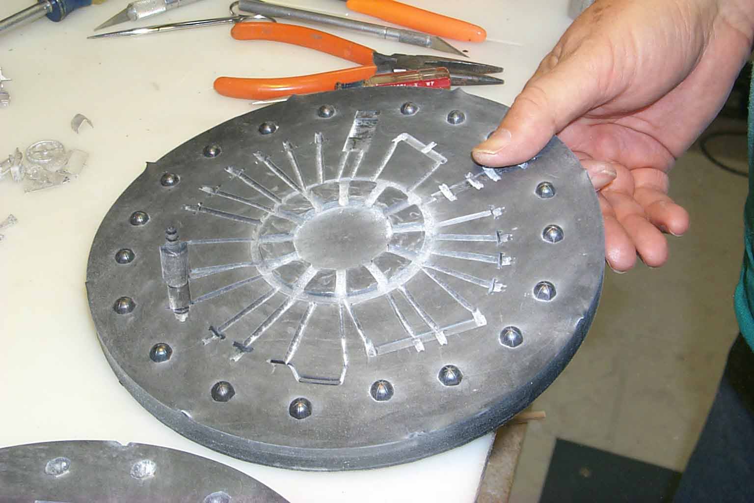
22. The "guts" exposed. Looks pretty good so far.
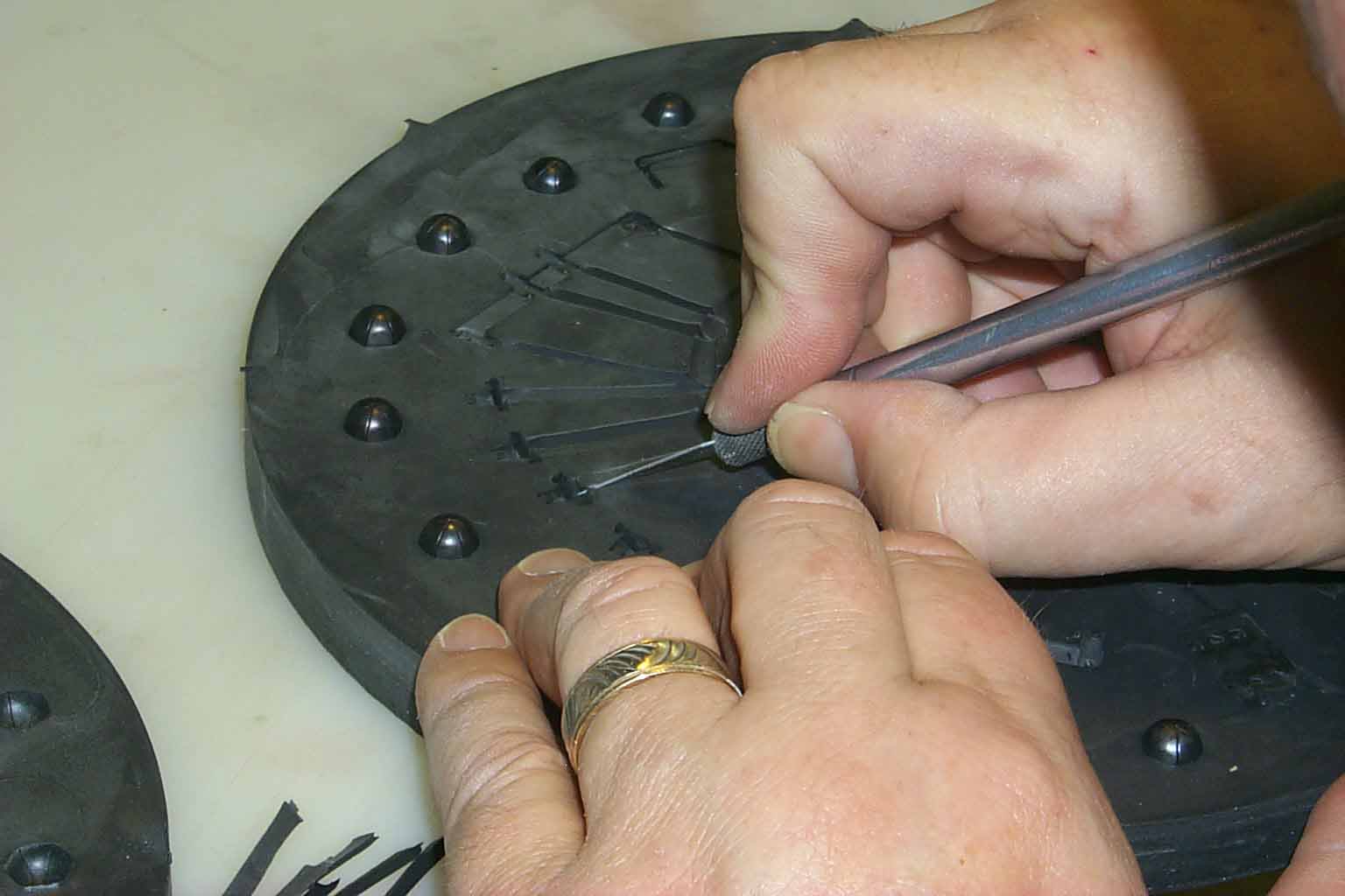
23. Removing the brass masters.
24. Sometimes pliers are needed to coax the parts out of the rubber.
25 26 27 28 29 30 31 32
25. Still pulling parts out.
26. One half of the finished mold, well almost finished, a bit more work to go.
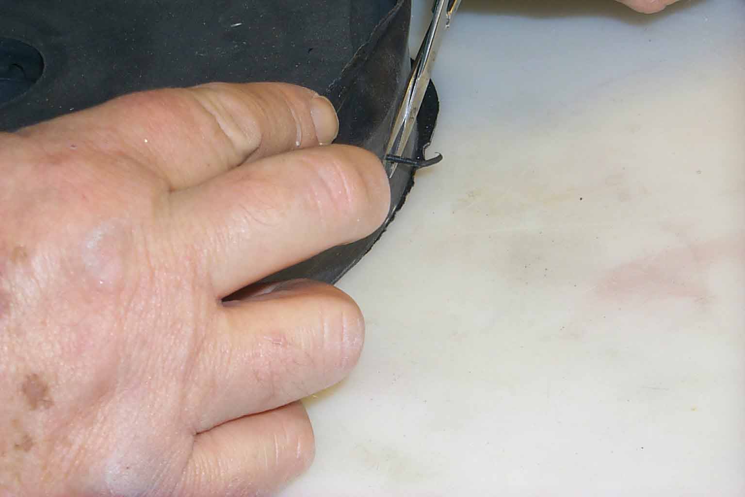
27. Cutting off the remnants of the "shoe strings"
28. Cutting off the rubber that tried to escape between the center ring and the top and bottom plates.
29. A little more trimming.
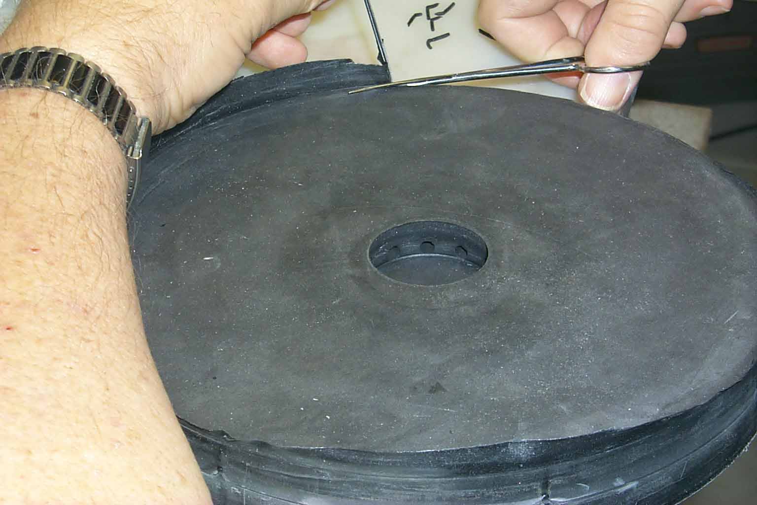
30. Adding a notch on the top and bottom so I know how the halves fit together.
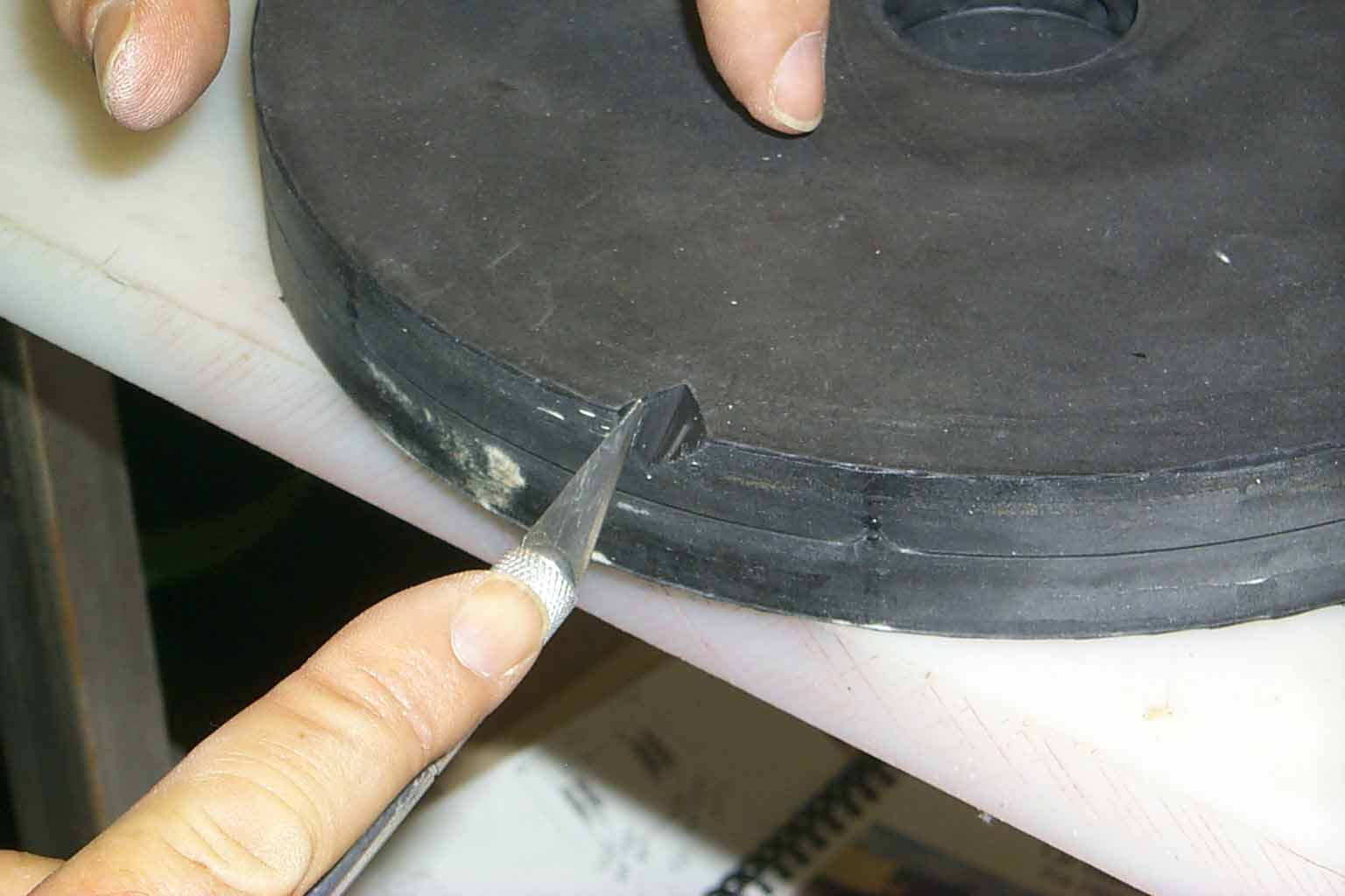
31. Starting to cut gates from the center to the cavities left by the brass masters.
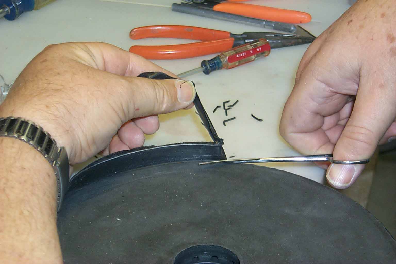
32. Still more gating. You need a VERY sharp blade to cut this rubber. It has the consistency and texture of a car tire.
Half way through this update!! Still with me???
33 34 35 36 37 38 39 40
33. Done with the gating.
34. A little talcum powder. Actually is baby powder but don't tell anyone!
35. Brushed with an old paint brush.
36. Into my Romanoff spin caster. The aluminum sheet inside is to catch some of the flash that sneaks out of the mold. The metal won't stick to the aluminum and falls off so I can put it back in the melting pot.
37. Locking down the top plate.
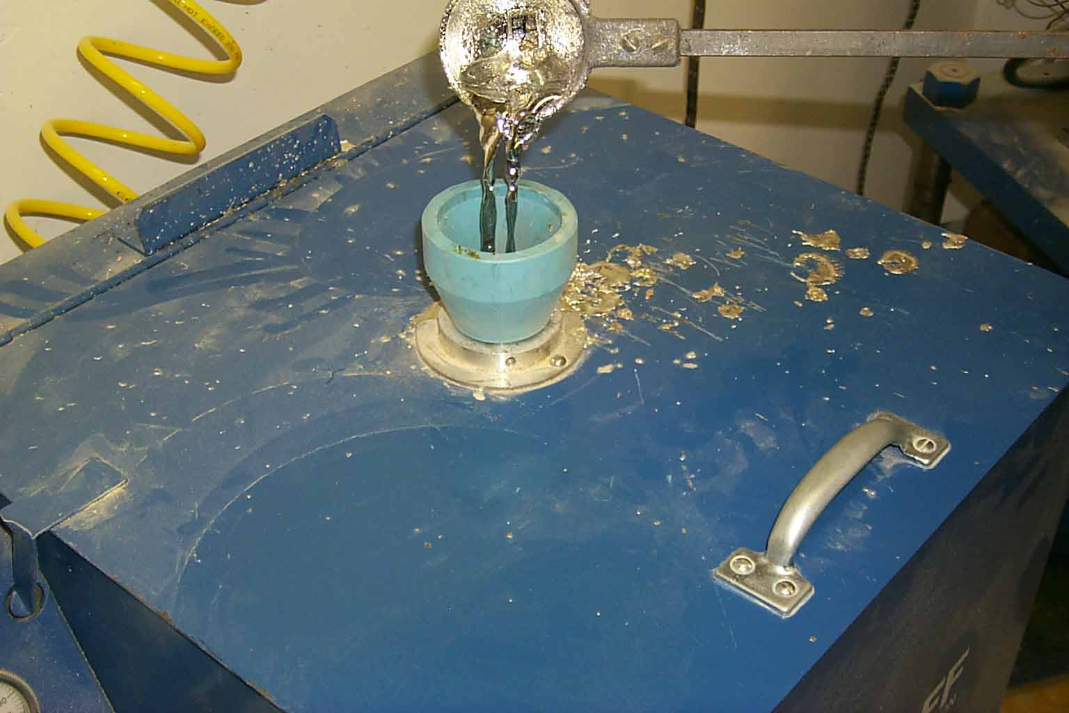
38. Door closed and pouring the hot metal in through the funnel.
39. 30 seconds later the door is open and locking plate removed.
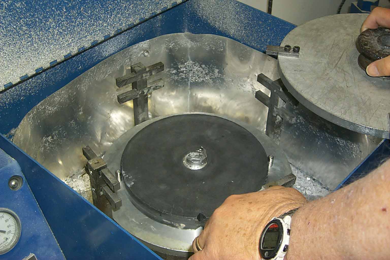
40. Mold on the bench ready to open.
41 42 43 44 45 46 47 48
41. Mold open, looks pretty good to me. All cavities filled so no "tweaking" to the gates.
42. A closer look.
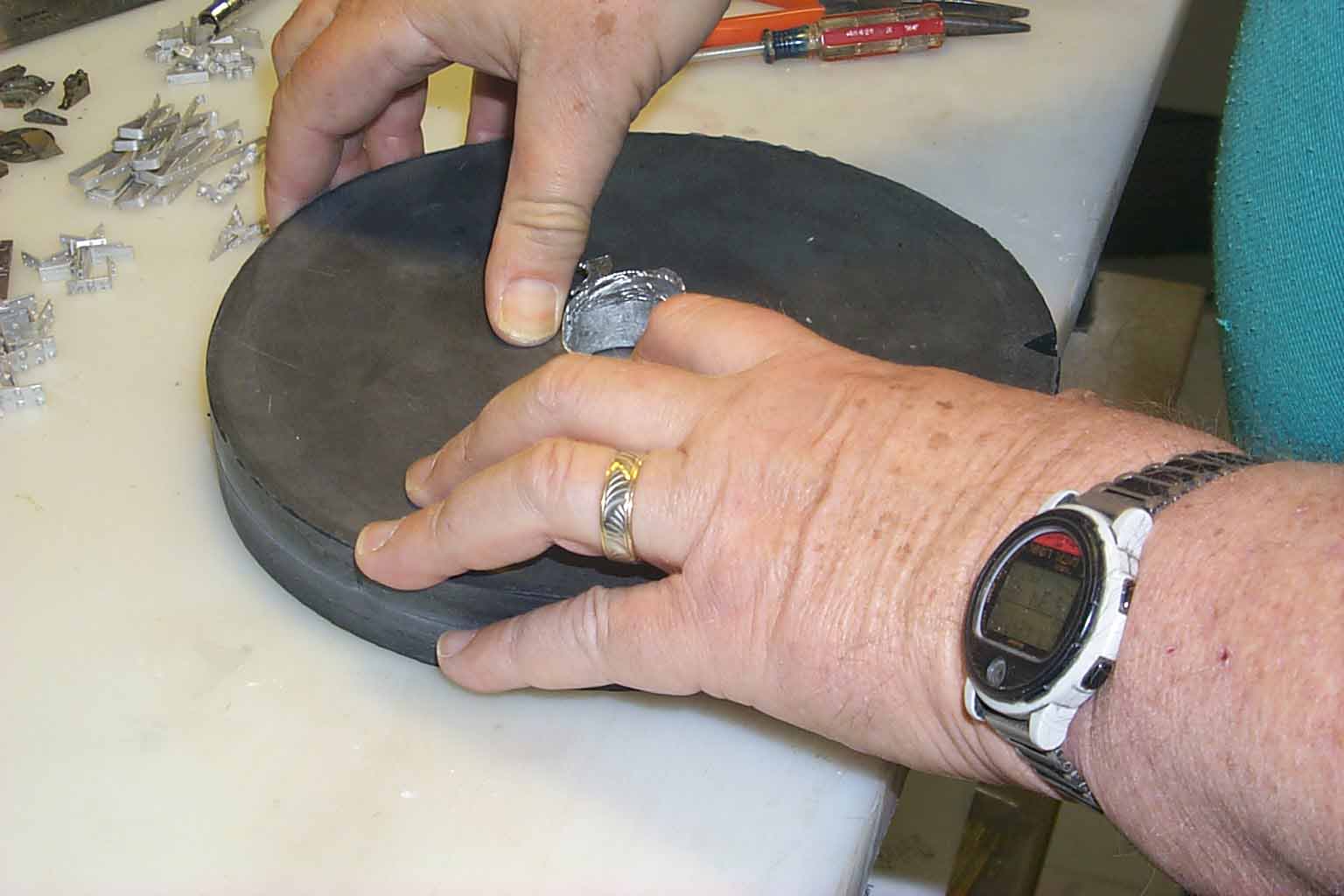
43. Removing the cast gate to go back in the melting pot.
44. Removing parts.
45. Fresh parts from the mold.
46. More parts from the same mold.
47. I made a total of 6 molds for all the DB parts. I did this while you weren't looking as picturing 5 more mold making processes would put you to sleep. In this picture, I'm adding the end caps to the needle beam / drop door stop beams.
48. Adding the lower frame corner brace.
49 50 51 52 53 54 55 56
49. Adding the yoke straps.
50. Adding the inside corner braces.
51. Adding the pillow block chain rollers with roller bar.
52. Adding the outside corner braces and the ratchet handle lock pawl.
53. Adding the ratchet handle and handle support.
54. Both the handles and supports.
55. Adding grabs and strap steps.
56. End view with parts added.
57 58 59 60 61 62 63 64
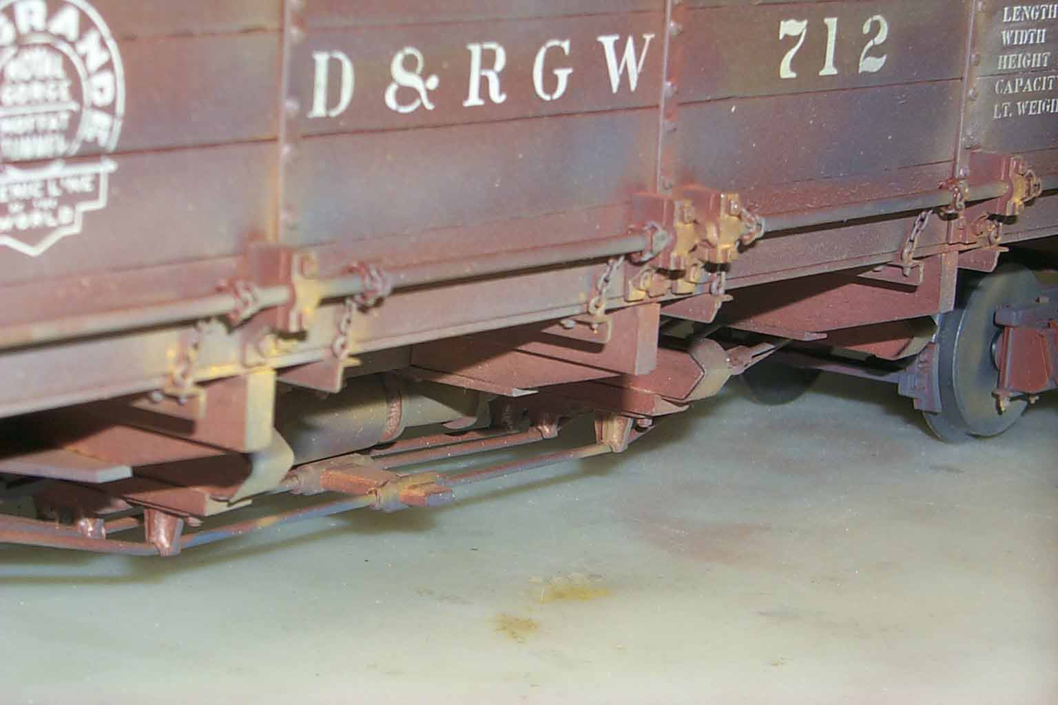
57. The finished bottom. Lot of pictures of the bottom but the bottom detail is a big part of this kit.
58. Painted, lettered and weathered side view.
59. The 2 center pillow blocks
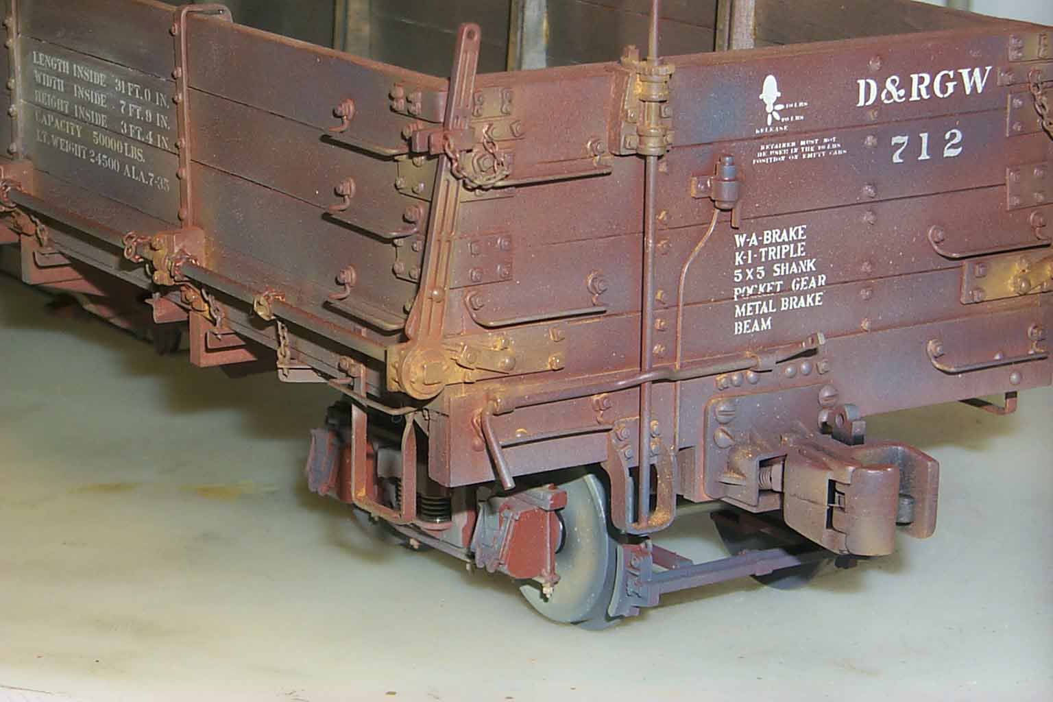
60. End corner with details.
61. "B" end of the car.
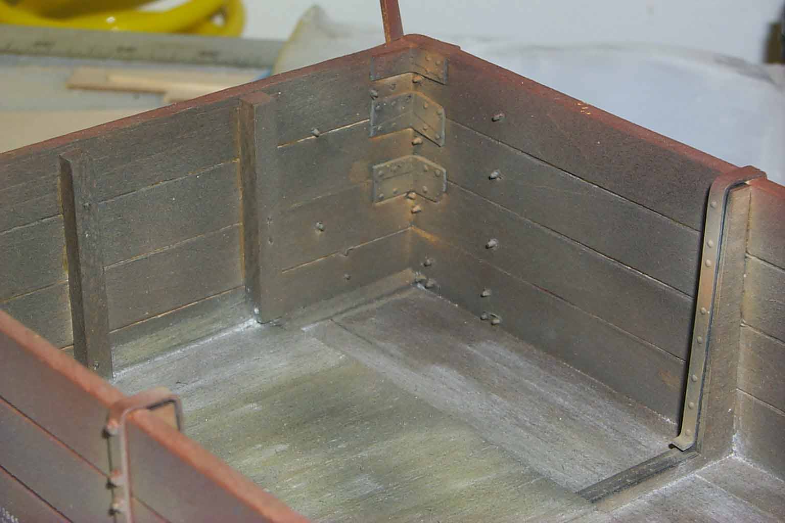
62. Inside view of one corner.
63. More of the bottom.
64. Angled side View.
So now your thinking, OK when do I order my kit. As hard as it might seem to believe, I still have more to do. I have ordered the lumber, metal and rods. I still have to make the frame jig and then build the second cut for production parts. The instructions get written during the build out of the second cut. With all the steps needed for this kit, I expect the instructions to be like the GRAMPS instruction, roughly 30 pages. Half of witch will be pictures.
On the next update, I'll show the frame jig and some laser cutting. That will wrap up this insight to my process of developing a new kit. I think you can see that while I have preserved Don's original ideas, this has been a ground up rebuild. As I mentioned earlier, I will make parts available to all of you with Don's kit that would like to update / upgrade some of the original pieces.
So for now I will sign off. I hope all are enjoying this trip.
See you next time.........................
Phil
Update 6, 6-26-2008
Lots of production and trains shows since the last update.
What we covered so far is the design and cutting of the brass masters for the spin casting molds. The parts that are missing is CAD work and lasering of parts, bending of all the brass parts, grabs, strap steps, lift bars, etc and packaging. While I will share the CAD and lasering, my custom bending brakes will have to remain a mystery. I don't allow pictures or drawings of those machines off the premise.
I use AutoCAD light for my CAD work. When Don and I got into the laser business, CAD became the next hurdle. Fortunately for me, Don was about 3 months ahead of me in getting his laser on line. Once mine was up we spent several hours on the phone reviewing the basic commands and drawing simple squares, circles and more complex items. Don was the teacher for these sessions. But like most programs, practice improves one's skills. I'm still a 2D kind of guy. I'm in the process of acquiring a CNC milling machine so 3D is on the horizon.
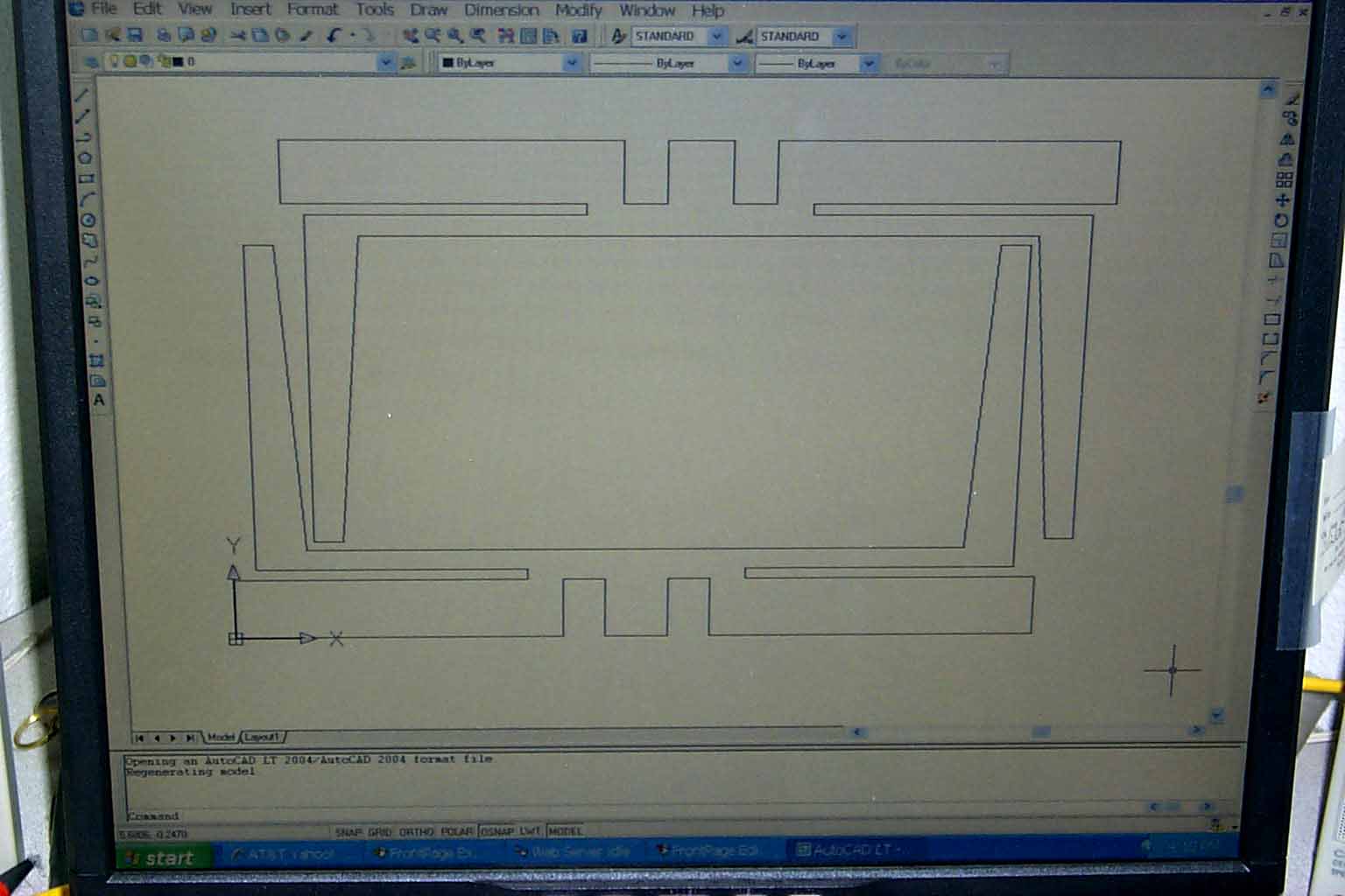
This is a picture of the end yokes for the drop bottom in AutoCAD. Lots of paper sketches and dimensions get laid down before I actually start drawing in CAD. Once I had a single drawing, I converted the .dwg to .dxf and from .dxf to a .txt file in "G" code. I then laser the single part to test it's validity. When I had "tweaked" the size and was satisfied, I did this drawing for production. I just copied the bottom yoke and rolled it 180 degree and pasted it back down. The conversion of .dwg to .dxf happens in AutoCAD. Then the file is imported to another program I use called Mach2.
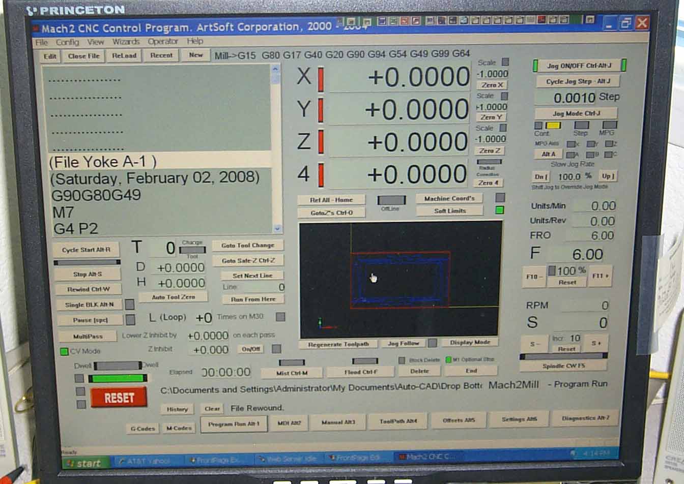
This is a snapshot of a MAch2 screen. Hard to see but the previous AutoCAD drawing is in blue inside the center black window. Mach2 has a section for importing .dxf files and turning them into a .txt file full of "G" code. "G" code is a primary language for running a CNC (computer numerical control) gantry or mill or lathe or a host of other machines. Without boring you, I'll give you a few of the commands used. In the upper left window you can see the (File Yoke A-1). That's just a title of the file and is an information line only. Below that is another information line with the date. The next line is basic default codes to reset or zero out any other residual commands that might affect the laser gantry.
The next line is M7. I use this to turn on the air pump that feeds the focusing lens to keep dust, smoke and any burnt material out of and away from the lens. The command also arms the laser. The next line is G4P2. G4 is a pause command and P2 is a timer. In this case, 2 seconds. The bulk of the code is not visible. If I were going to write a simple program to laser out a 1" by 1" square hole, it would look like this:
M7 (arm the laser and turn on the air pump)
G4P2 (pause 2 seconds)
F50 (cutting speed to be 50" per minute)
G0 X0.0000 Y0.0000 (go rapidly to coordinates X=0.000 and Y= 0.000 if not already there)
M3 (turn on laser beam)
G1 X1.000 Y0.000 (go right 1" and no change in Y)
G1 X1.000 Y1.000 (no change in X but go up 1")
G1 X0.000 Y1.000 (go left 1" and no change in Y)
G1 X0.000 Y0.000 (no change in X but go down 1". This is the starting point)
M5 (shut down laser beam)
M30 (shut down air pump and disarm laser)
There's lot more "G" and "M" commands is use. Some commands cause clockwise circles or arc's, some counterclockwise. Some control subroutines and on and on. But I think you get the idea. Beside the "G" codes, every time I change the type or thickness of the wood, cutting speed needs to be adjusted and the lens needs to be adjusted to keep the focal point correct. Birch plywood is harder to cut than poplar, regardless of it's thickness. All things one learns when "driving" any sort of machinery.
So, now we have a CAD drawing and have converted it to a usable code to drive the gantry on the laser. Lets cut those parts out.
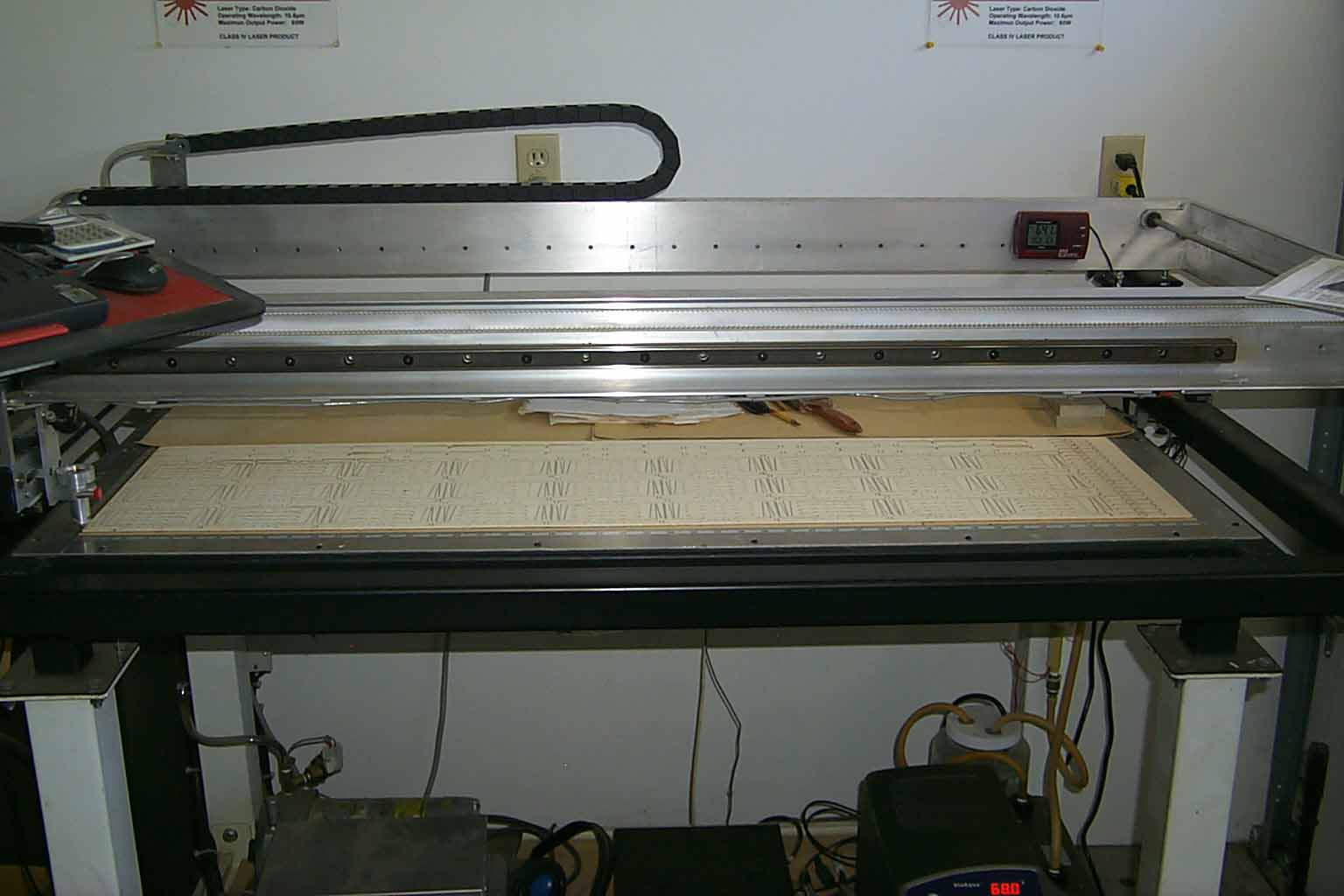
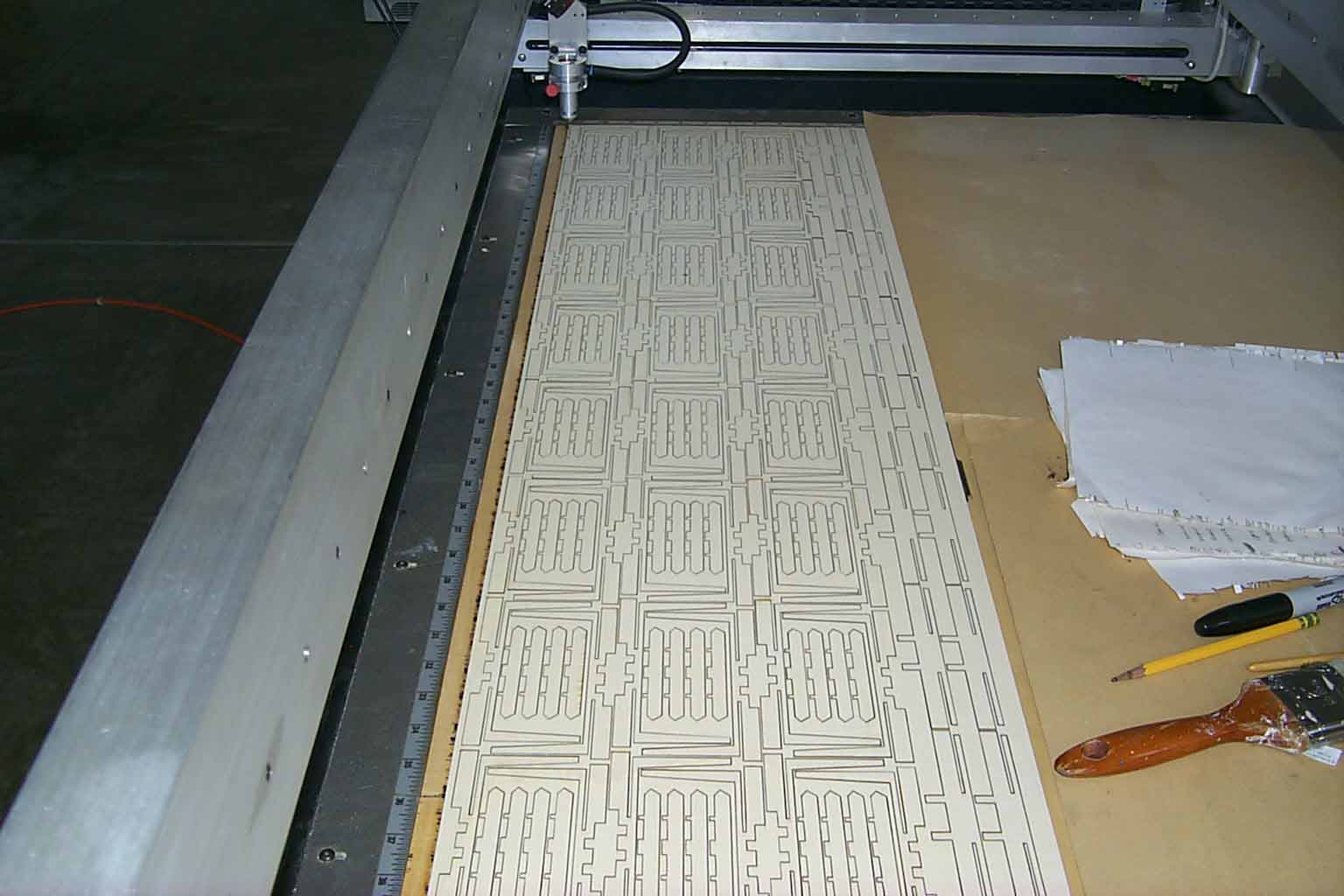
Here you can see a whole sheet of plywood with parts cut out. A very important part of lasering or any cutting is the economy of the raw material. As you can see, the yokes are interlaced with needle beams and end beams. I do not like throwing away good lumber.
This is only a couple parts in the drop bottom project but I think you can get the picture. When I do a run of 30 kits, I can expect to run the laser 8 hours a day for 3 days. Casting takes another 2 full days. I try to do all the brass bending while the laser is running. Packaging takes another full day. Then add the cost of the packaging material and printing of the instructions.
After 37 years in the communications business and working for "the man", I enjoy being my own boss, running my own hours, quality control and everything else it takes. But the best part is still going to conventions to meet the folks that buy these kits and make it all possible.
I hope you have enjoyed this "behind the scenes" look at a portion of what it takes to produce a kit.
Phil